Plans Pro guide
This guide takes you step by step through Plans Pro, from creating a project to exporting your plans. It follows a complete project: a two-storey house with a basement, and then opening an existing IFC file.
All you need is your Art Construction account. Open Plans Pro at art-construction.ch/plans/pro, then click “Se connecter” (Sign in). All images were taken in the current version of Plans Pro, with a demo account.
Part 1 – Create a project from scratch
1. Create the project
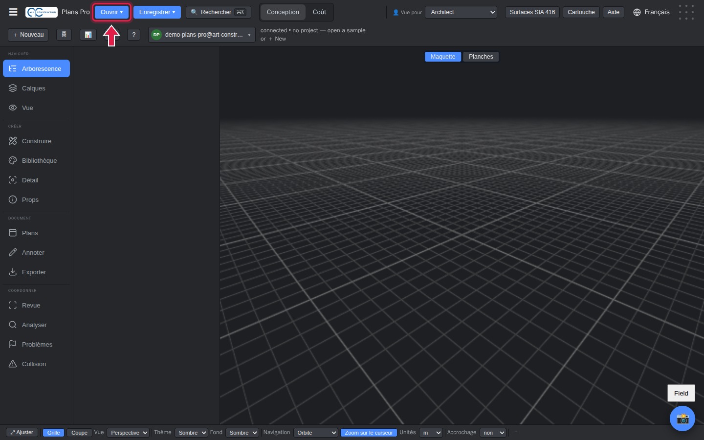
1Open the “Ouvrir” (Open) menu
Once signed in, click Ouvrir (Open), at the top left.
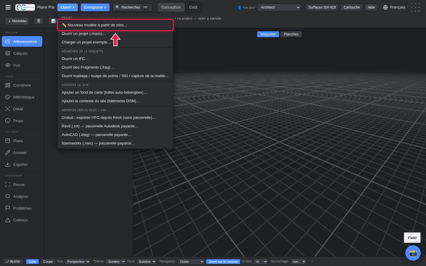
2New model from scratch
Choose Nouveau modèle à partir de zéro (New model from scratch), at the very top of the menu.
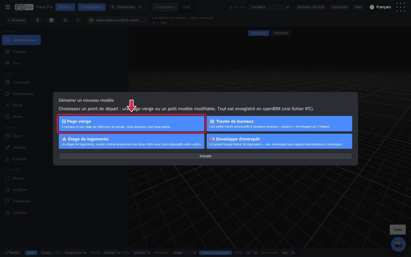
3Choose “Page vierge” (Blank page)
Click Page vierge (Blank page). Plans Pro sets up three levels and a reference slab for the site.
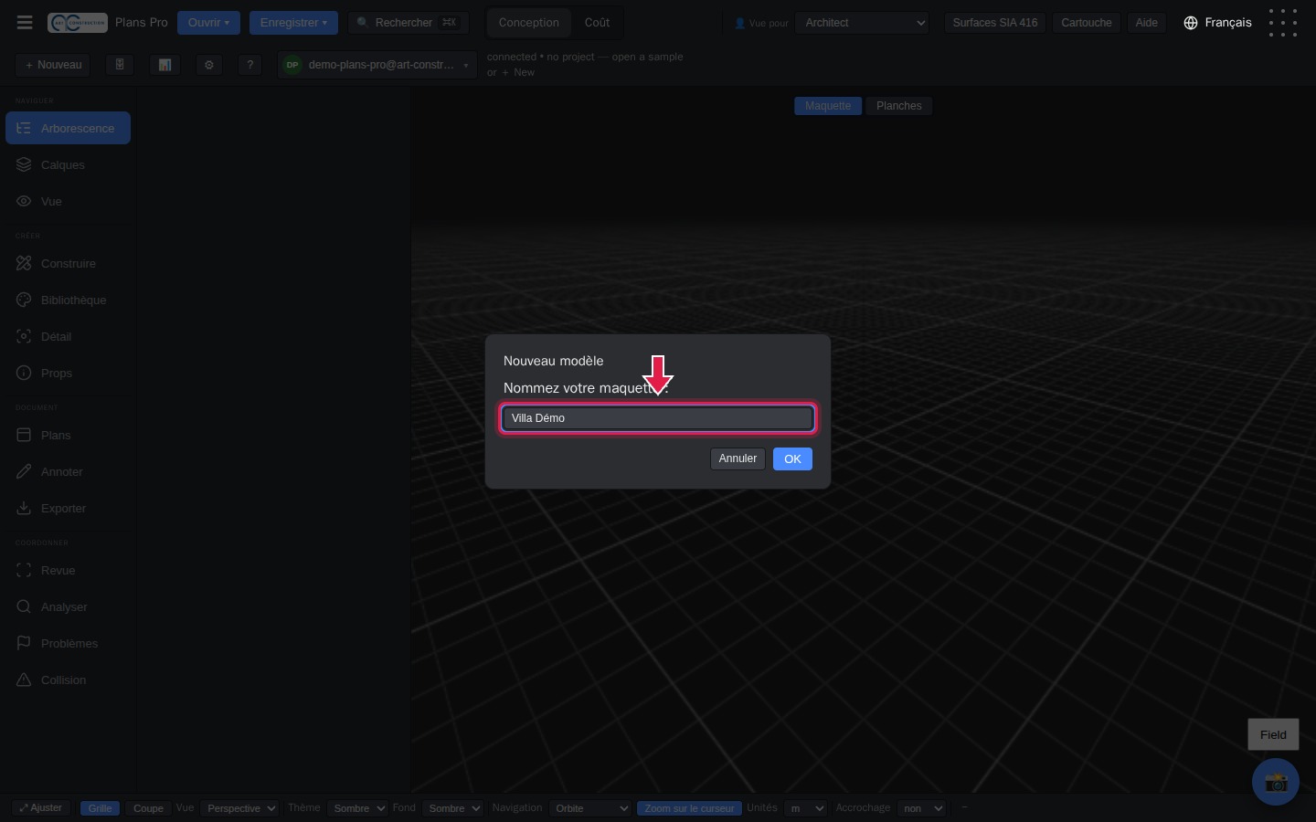
4Name the project
Type the project name, for example “Villa Démo”, then press Entrée.
5The project is ready
The project opens in the 3D model, with the Construire (Build) panel on the left. The project name appears at the top, in the project list.
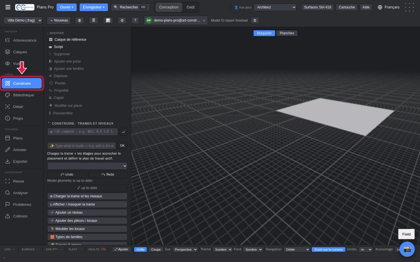
6Metric units
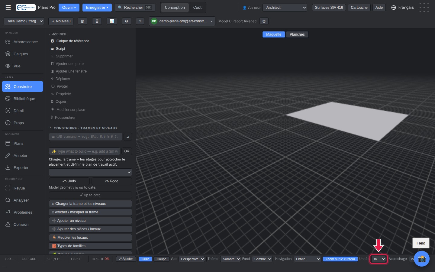
Plans Pro always works in metres: all dimensions are entered in metres (for example 2.8 for 2.80 m). The Unités (Units) option, at the bottom of the screen, only changes how coordinates are displayed (m, cm or mm).
2. Levels
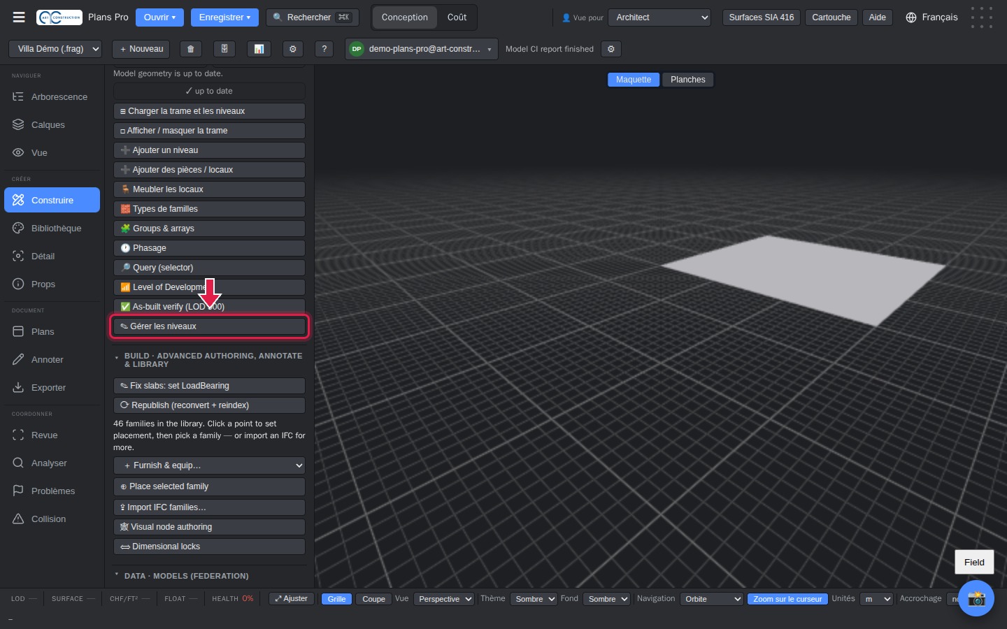
7Manage levels
In Construire (Build), click Gérer les niveaux (Manage levels). The list of levels opens, with their names and elevations.
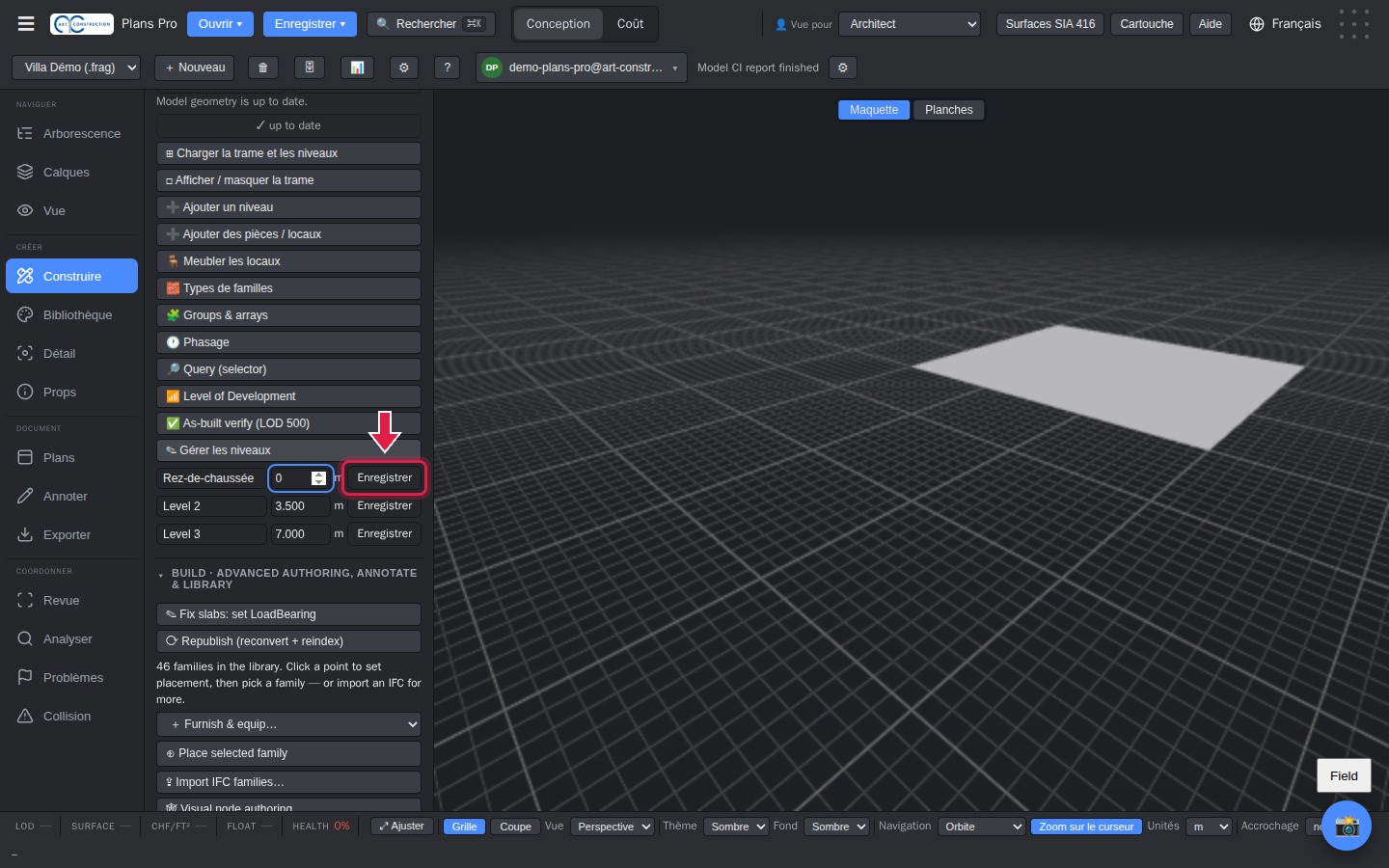
8Rename and position the levels
Give each level a name and an elevation: Rez-de-chaussée (ground floor) 0, Étage (upper floor) 3, Sous-sol (basement) −3. Click Enregistrer (Save) on the row you changed.
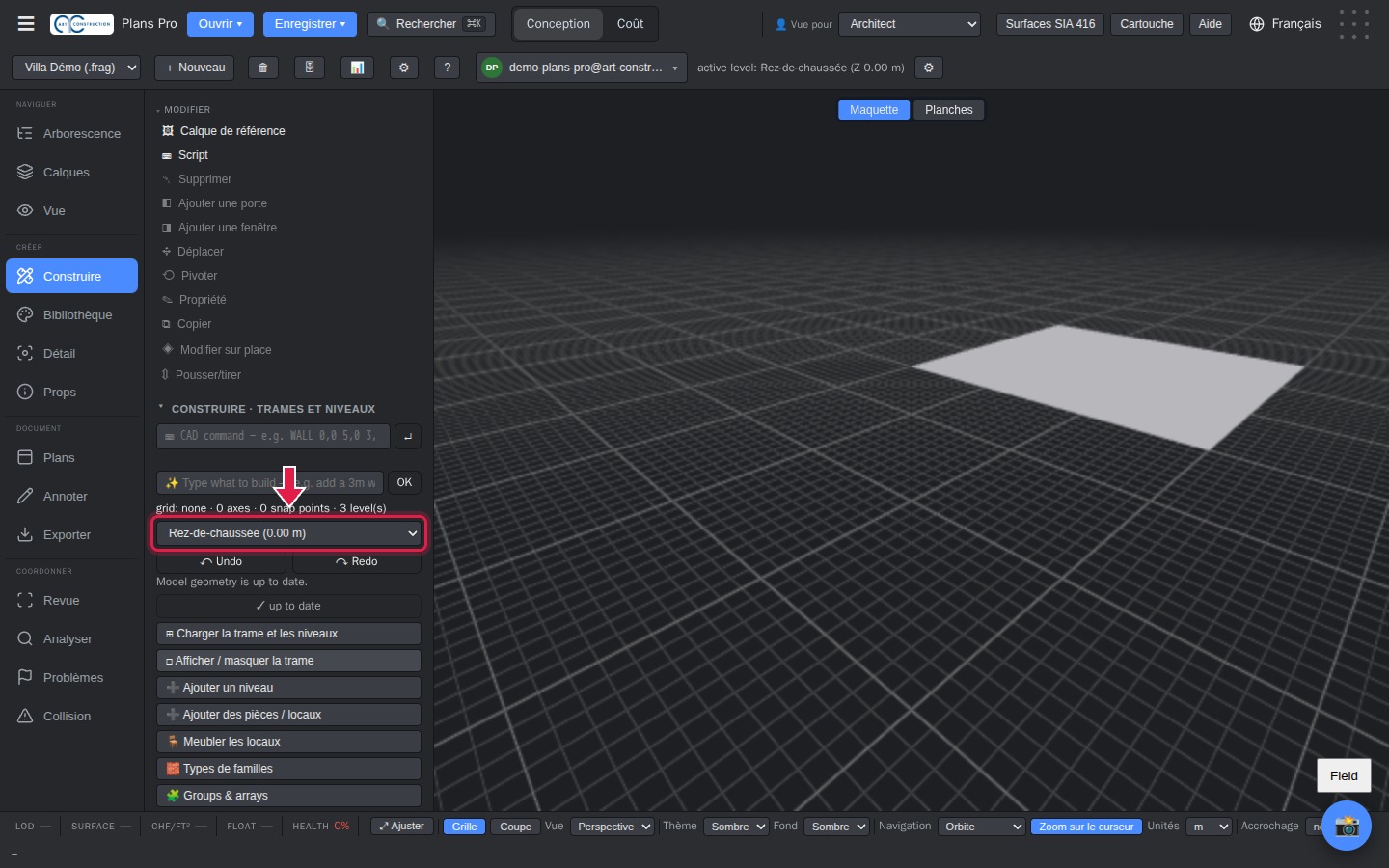
9Choose the working level
Click Charger la trame et les niveaux (Load grid and levels), then choose the level from the list. Everything you draw next goes on this level.
3. Walls
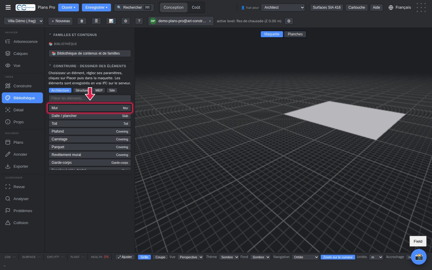
10The Wall tool
Open Bibliothèque (Library), on the left. Under “Construire · Dessiner des éléments” (Build · Draw elements), click Mur (Wall).
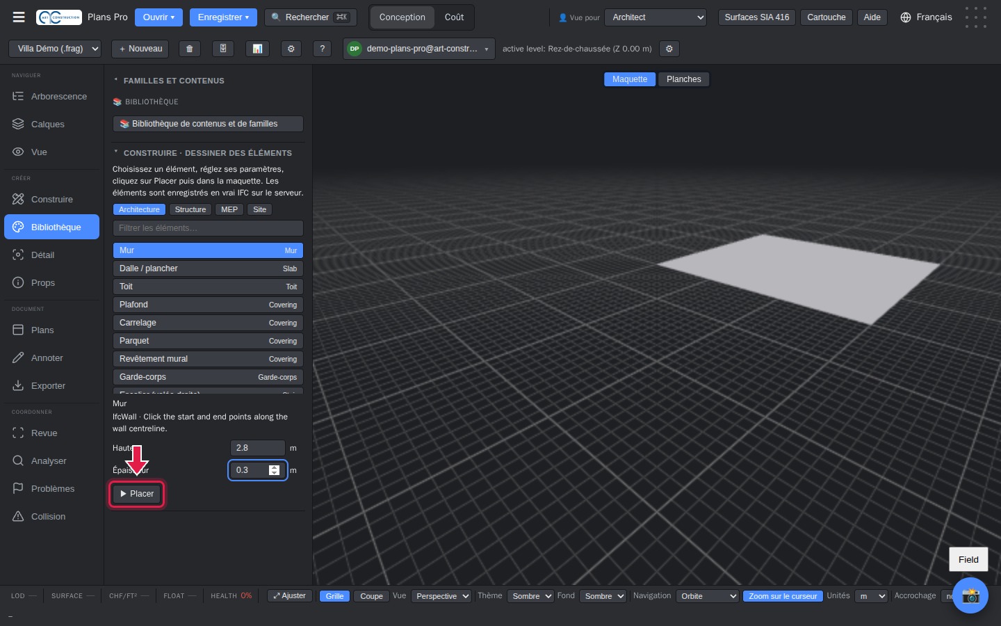
11Height, thickness, then Place
Set the wall height (for example 2.8) and thickness (0.3). Click Placer (Place), then click twice in the model: at the start and then at the end of the wall.
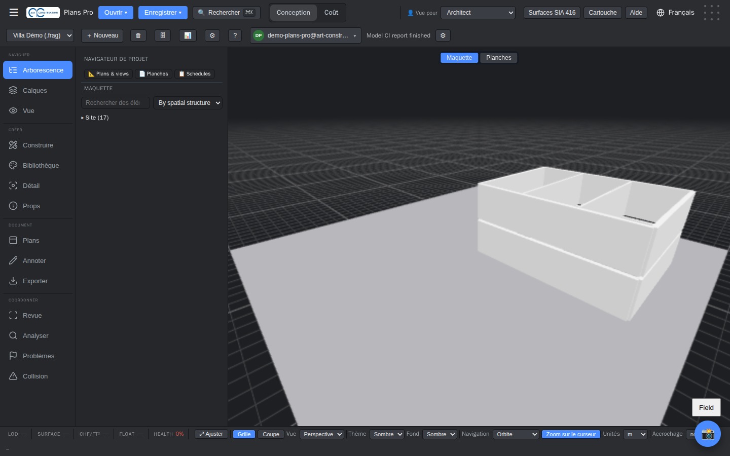
12All the walls
Repeat for each wall and each level. In the example: a 12 × 9 m house, 30 cm exterior walls and a few 15 cm partitions.
4. Slabs and columns
13Slabs
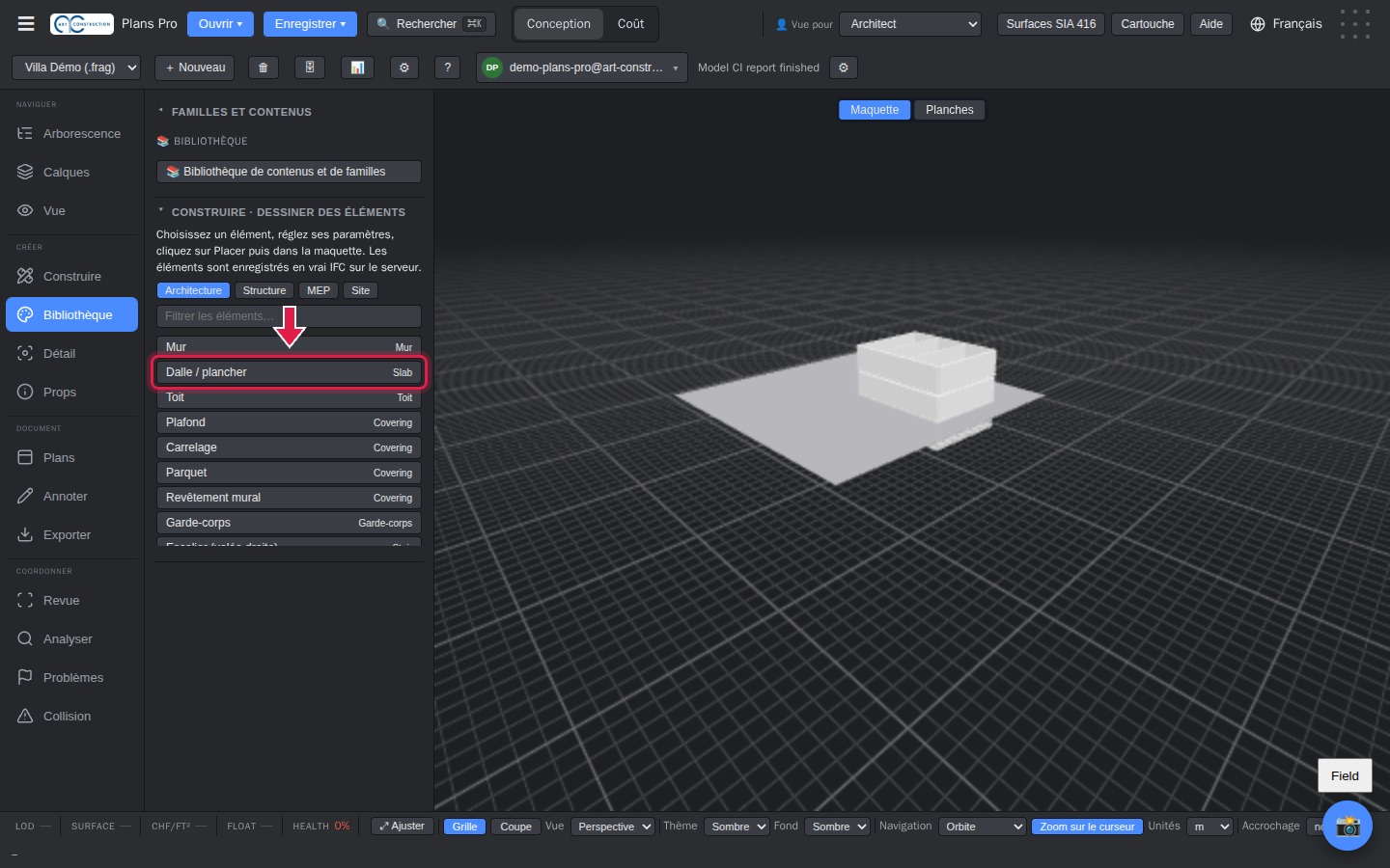
Choose Dalle / plancher (Slab / floor), set the thickness, then click Placer (Place). Click the corners of the slab in the model and double-click the last corner to close it. Make one slab per level.
14Columns
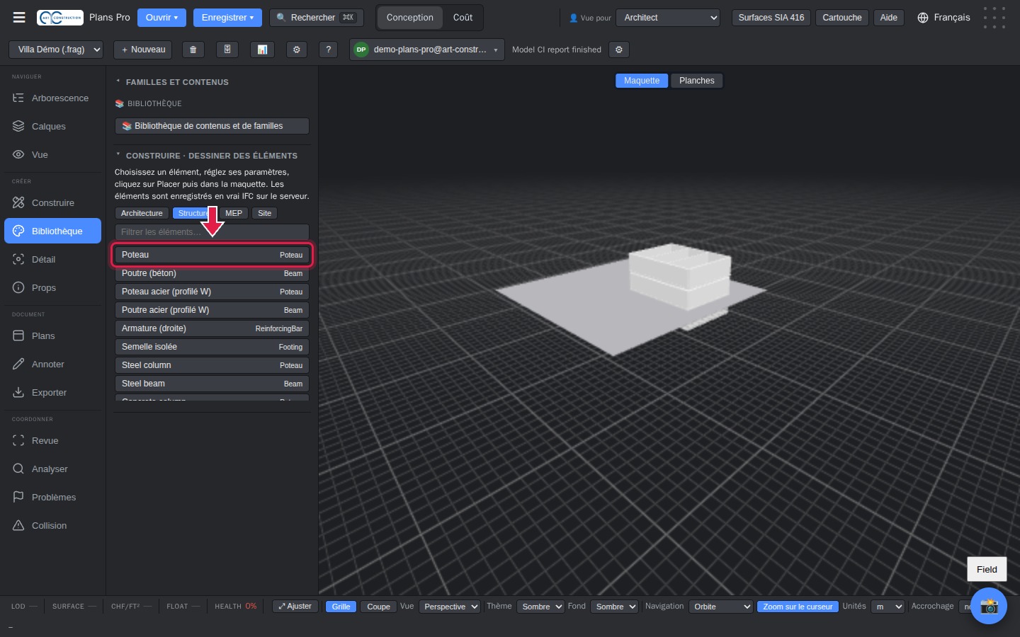
Click Structure (Structure), then Poteau (Column). Set its height and cross-section, click Placer (Place), then click where the column goes.
5. Doors and windows
15Add a door
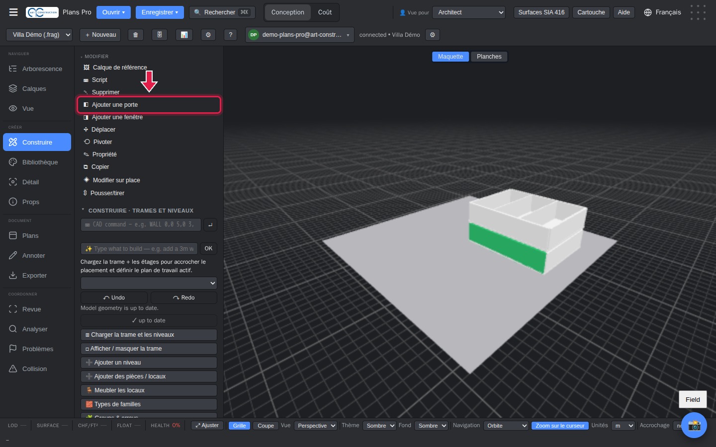
Click a wall in the model: it turns green. In Construire (Build), under “Modifier” (Edit), click Ajouter une porte (Add a door). The door is placed where you clicked on the wall.
16Add a window
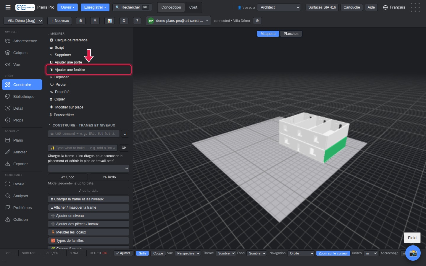
Same thing for a window: select the wall, then click Ajouter une fenêtre (Add a window).
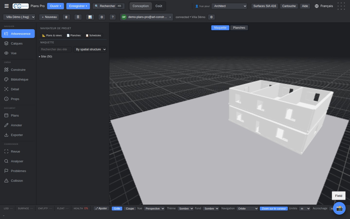
17The result
The openings are cut into the walls.
6. Rooms and SIA 416 areas
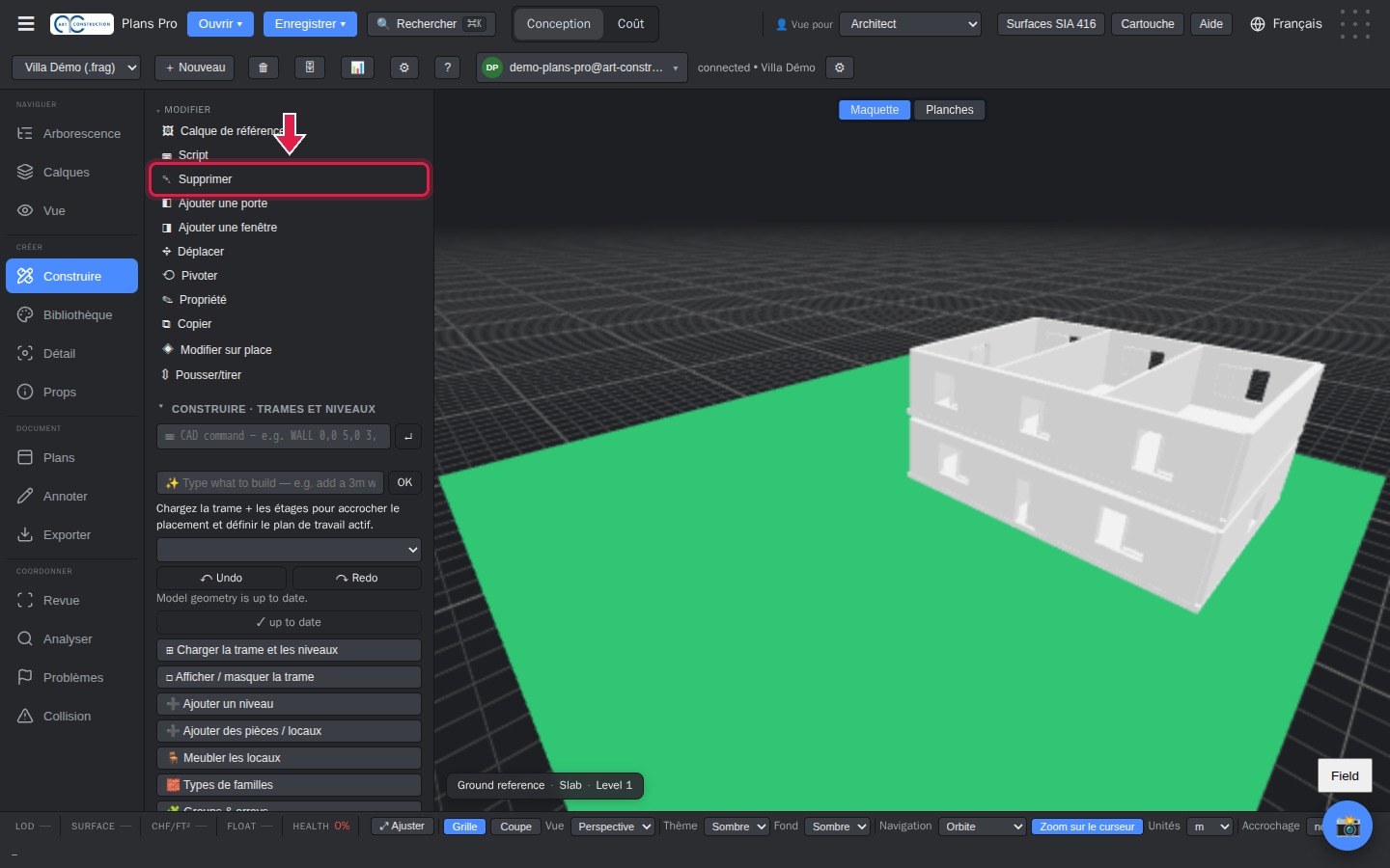
18Delete the site reference slab
The “Page vierge” (Blank page) contains a large 30 × 30 m slab that represents the site. Select it, click Supprimer (Delete) and confirm. Otherwise, the rooms would be calculated over its whole area.
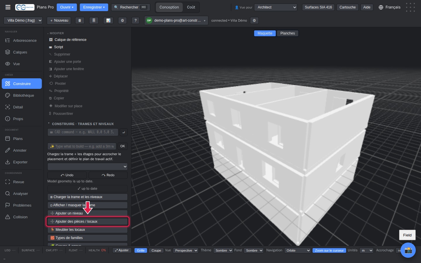
19Add the rooms
In Construire (Build), click Ajouter des pièces / locaux (Add rooms / spaces).
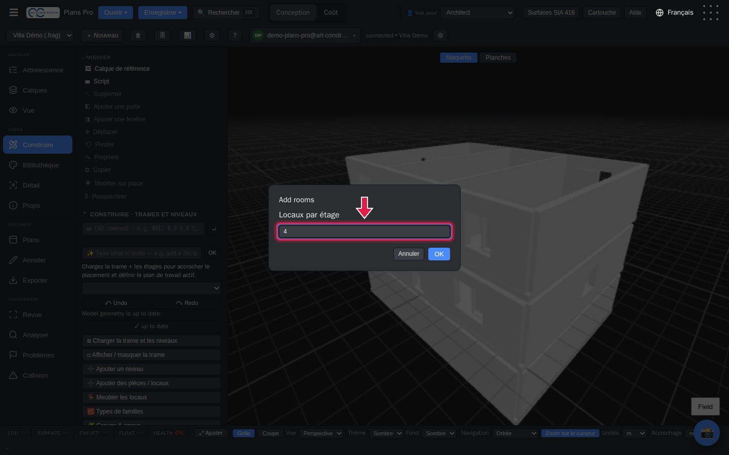
20Number of rooms and height
Enter the number of rooms per level, then the ceiling height. Plans Pro divides each level into regular rooms, inside the exterior walls.
21SIA 416 category of a room
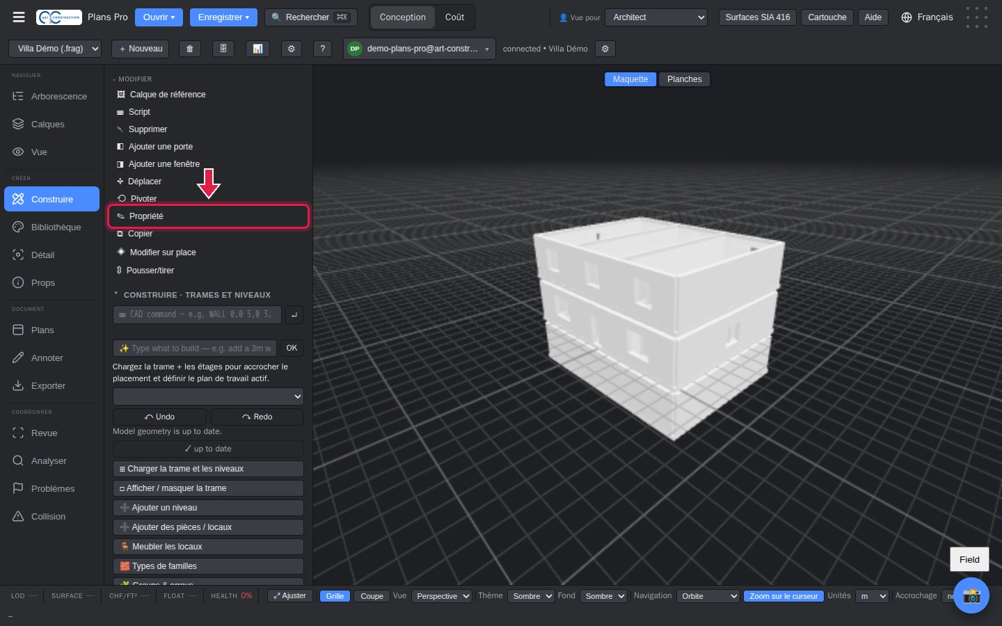
Select a room, then click Propriété (Property) under “Modifier” (Edit).
22Enter the category
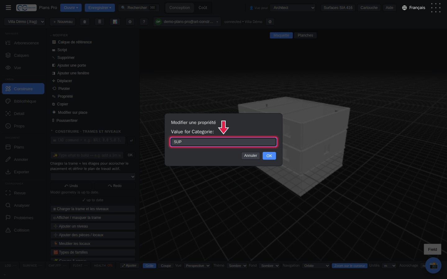
Answer the three questions: Pset_ArtConstruction_SIA416, then Categorie, then the category: SUP (main usable area), SUS (secondary usable area), SD (circulation area) or SI (services area).
23The area table
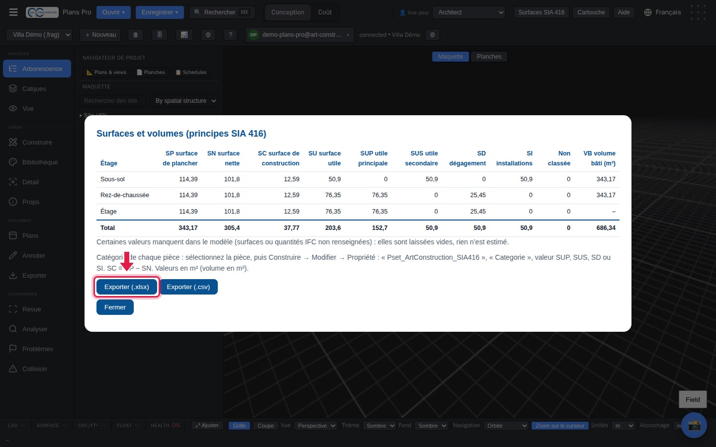
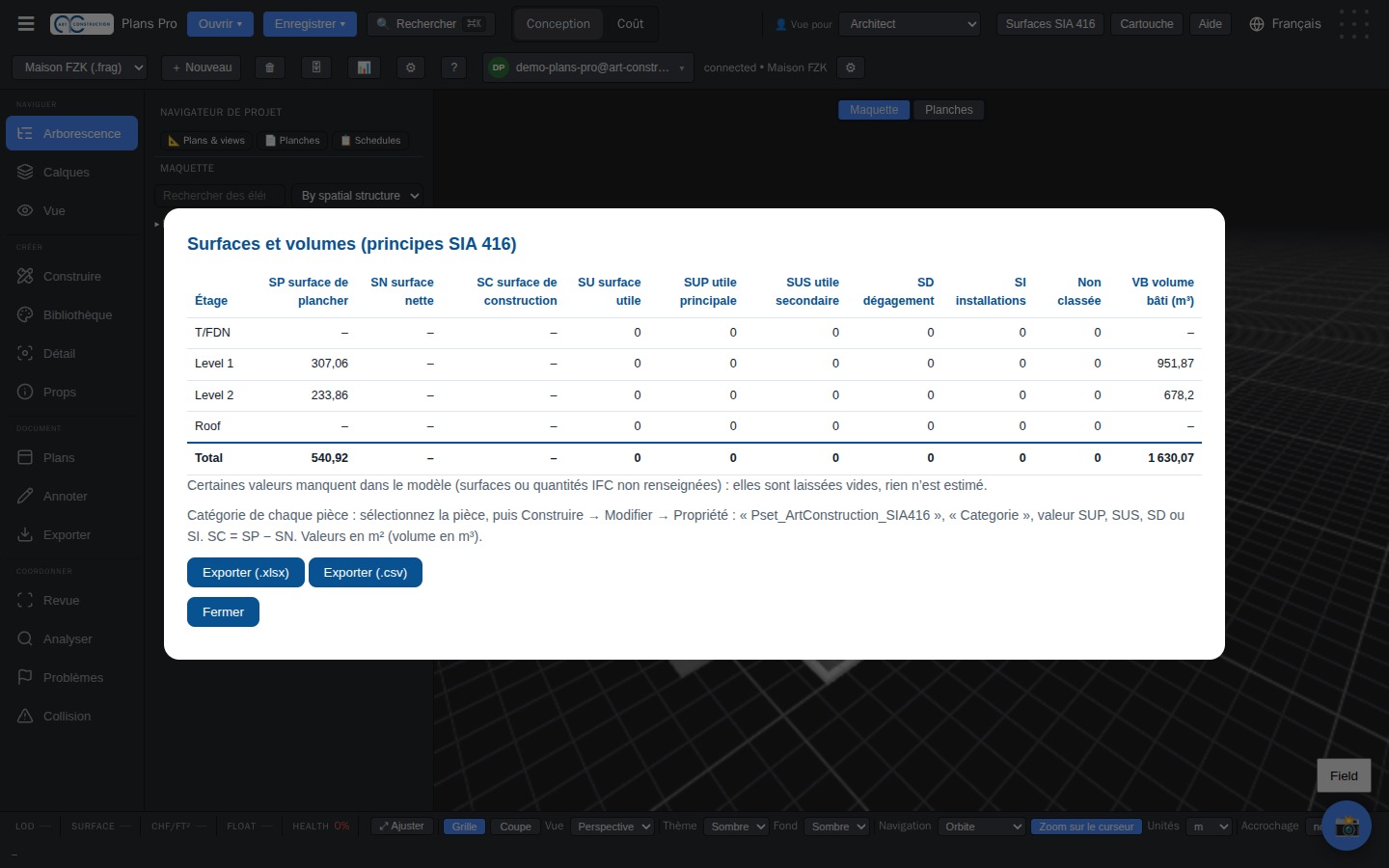
Click Surfaces SIA 416 (SIA 416 areas), at the top. The table gives SP, SN, SC, SU, SUP, SUS, SD, SI and VB per level. You can export it to Excel (.xlsx) or .csv.
7. CFC / eCCC codes
24Classify an element
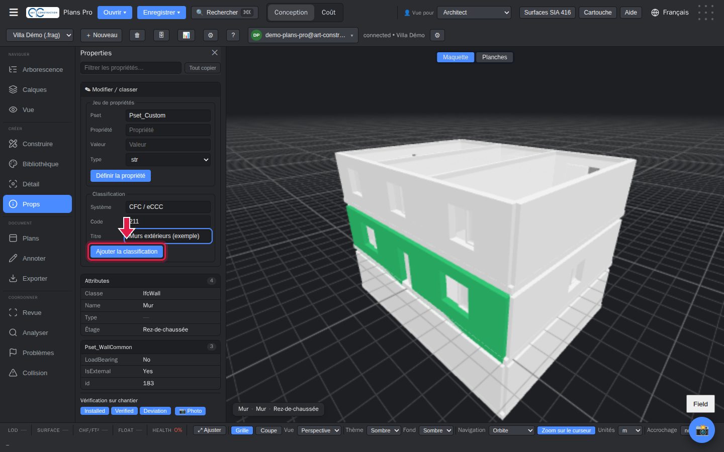
Select an element, open Props then Modifier / classer (Edit / classify). Under “Classification”, the system is already “CFC / eCCC”: type your code and a title, then click Ajouter la classification (Add classification).
8. The roof
25Add the roof level
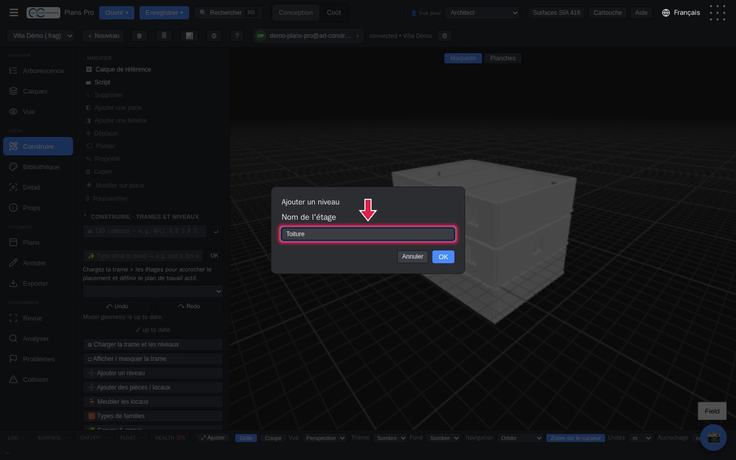
In Construire (Build), click Ajouter un niveau (Add a level). Type “Toiture” (Roof), then its elevation (6.0).
26Draw the roof
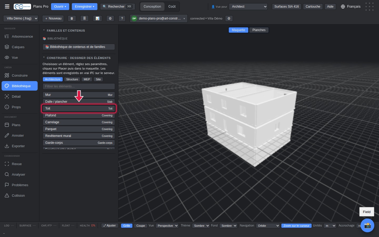
Choose the Toiture level, then Toit (Roof) in the library. Click the corners of the roof and double-click to close it. Plans Pro draws flat roofs.
27The house in 3D
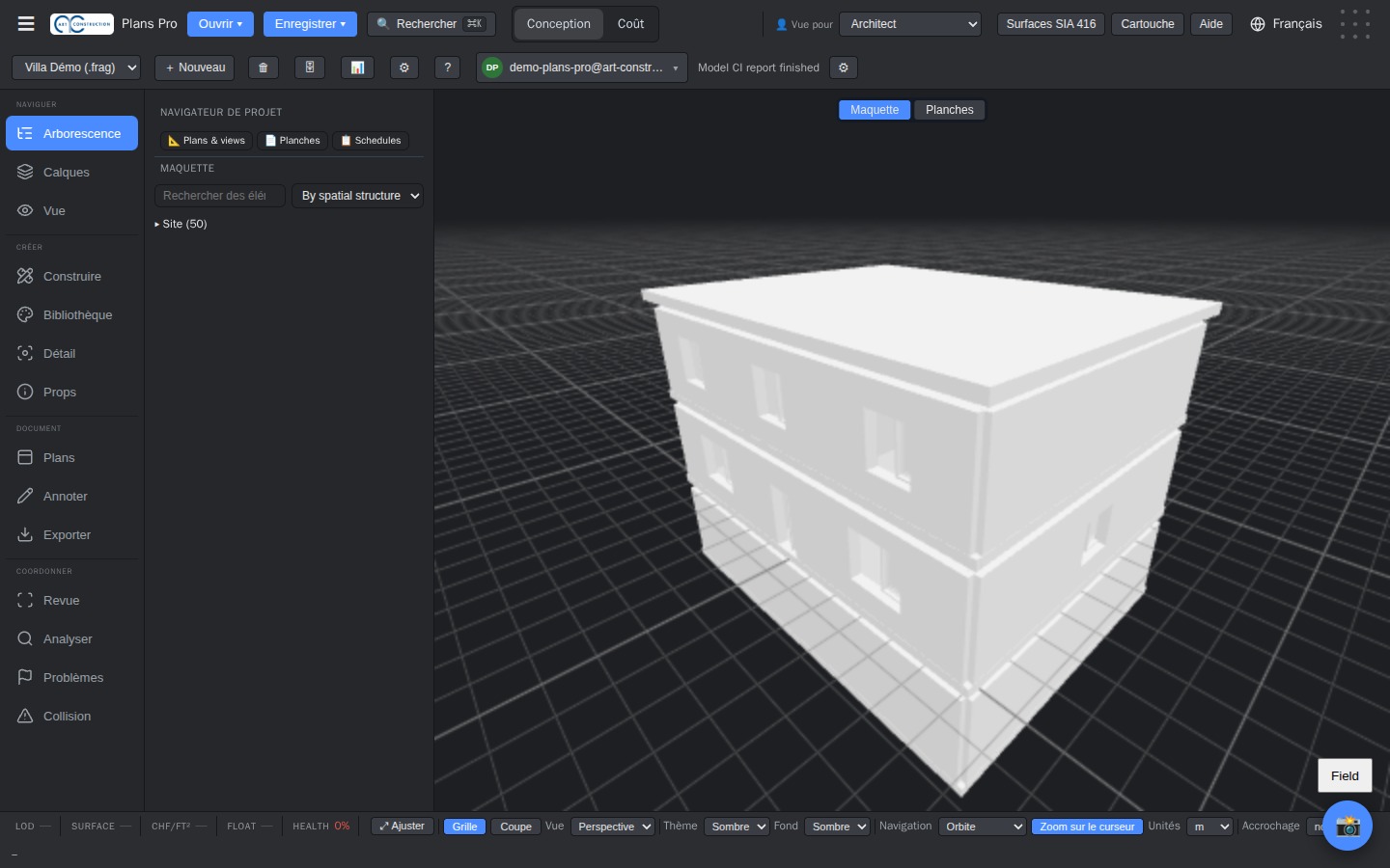
The model is complete. Rotate it with the mouse; the F key reframes the view.
9. Plans, sections and elevations
28The set of plans
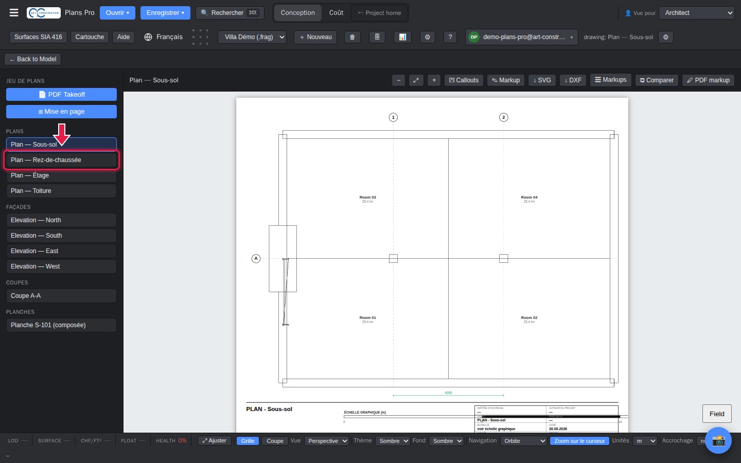
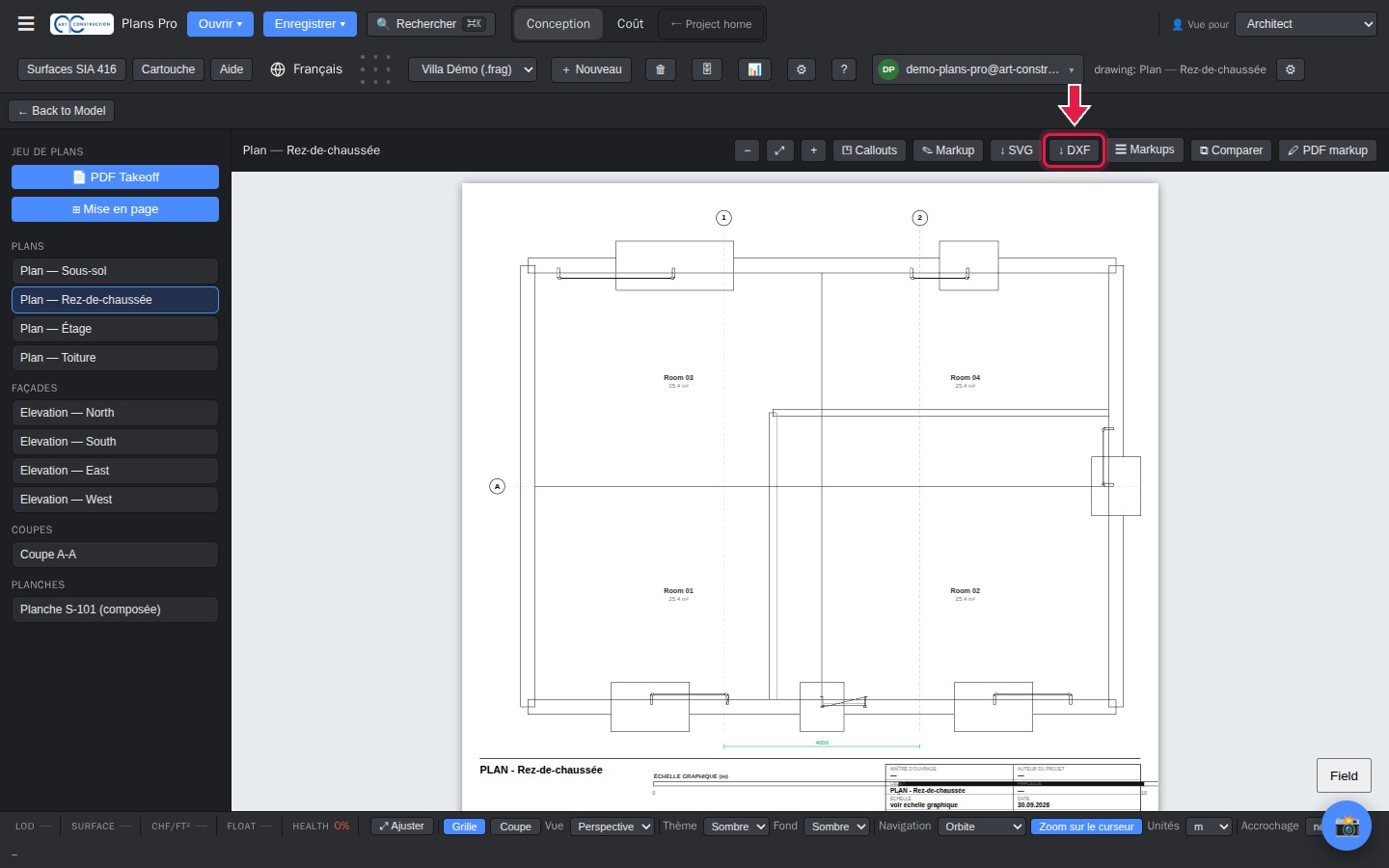
Click Plans (Plans), on the left. The list offers one plan per level, the four elevations and a section. Click a plan to display it.
29The plan of a level
The plan is displayed with the walls, openings, rooms and their areas. The ↓ DXF button downloads it for your CAD software.
30Elevations
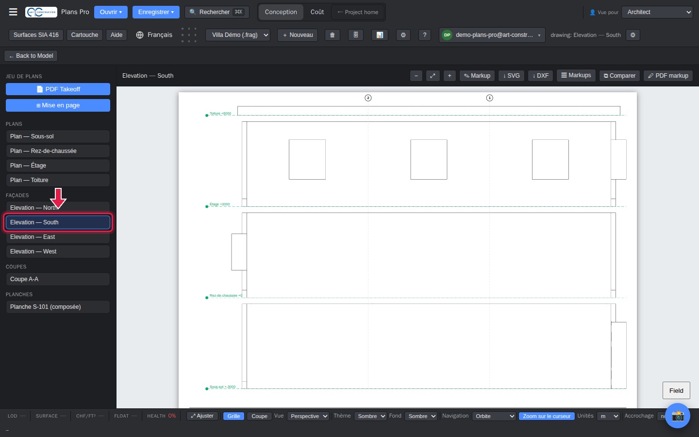
Click an elevation (North, South, East, West).
31Sections
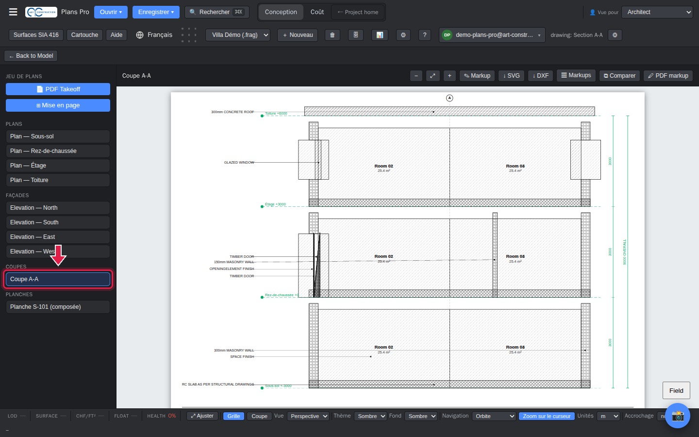
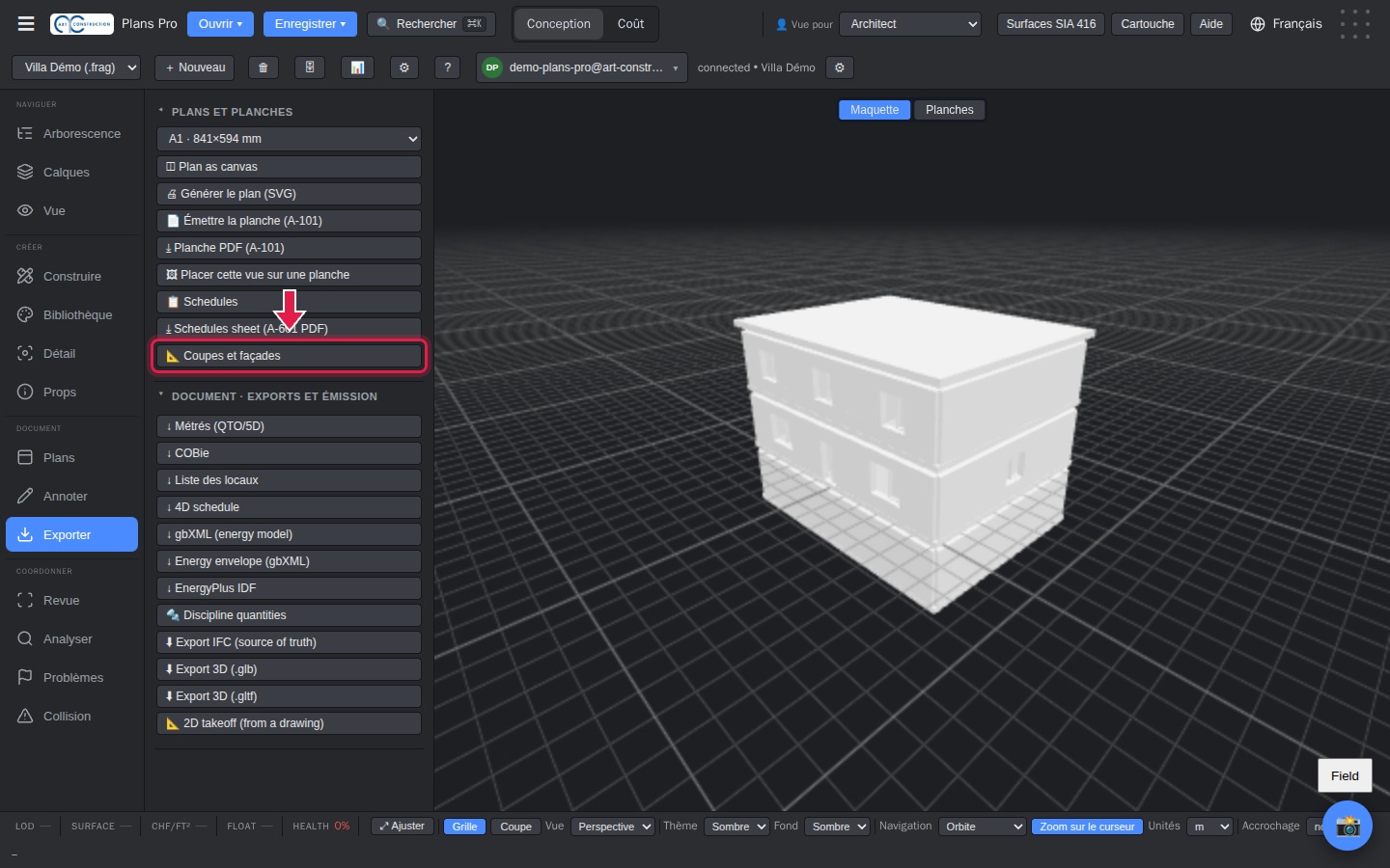
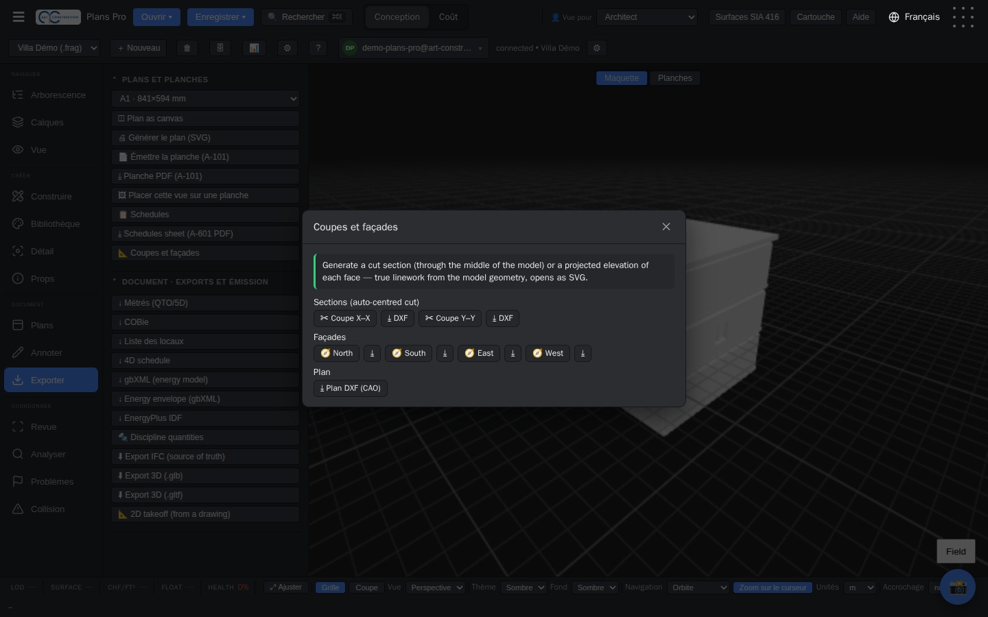
Click Coupe A-A (Section A-A) in the list: Plans Pro cuts the building through its middle. For sections in both directions, open Exporter (Export), expand “Plans et planches” (Plans and sheets) and click Coupes et façades (Sections and elevations); each section opens in a new tab.
10. Title block and A3 layout
32Fill in the title block
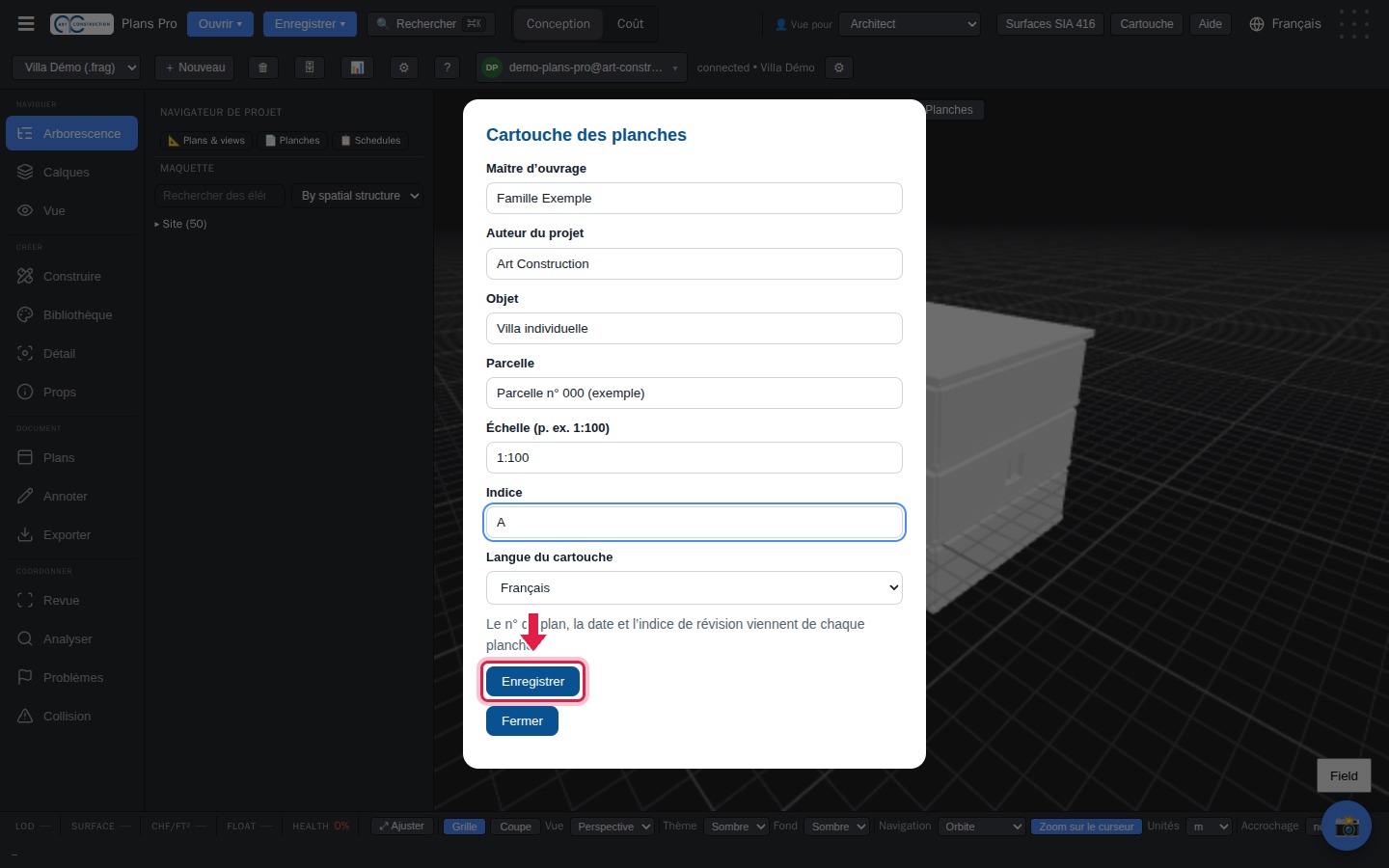
Click Cartouche (Title block), at the top. Fill in the client, the project author, the subject, the plot, the scale and the revision, then click Enregistrer (Save). The drawing number and the date are filled in automatically.
33Choose the A3 format
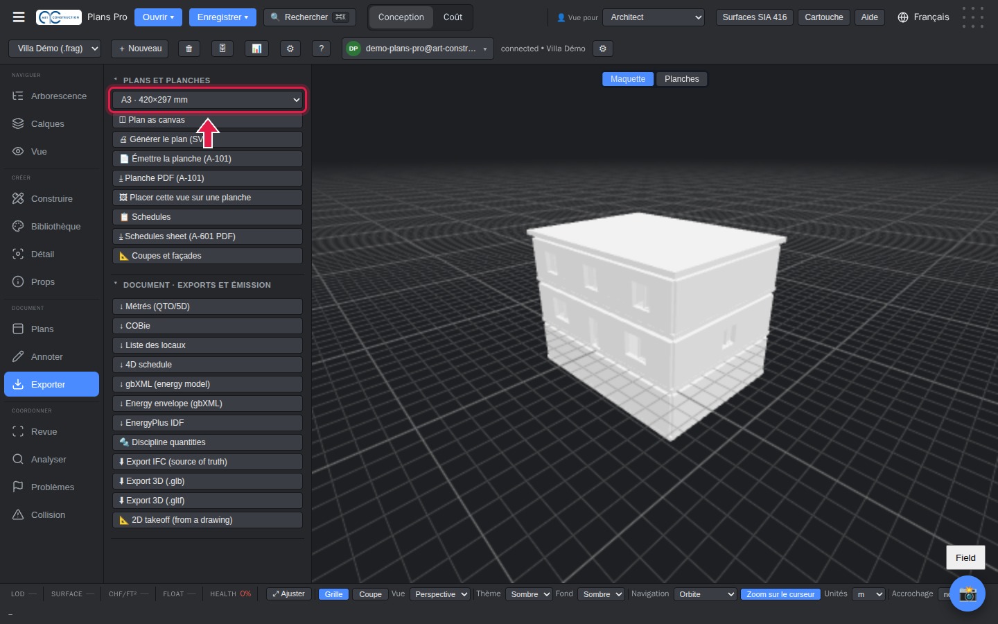
In Exporter (Export), under “Plans et planches” (Plans and sheets), choose the A3 · 420×297 mm format. Formats A0 to A4 are available.
34Create the PDF sheet
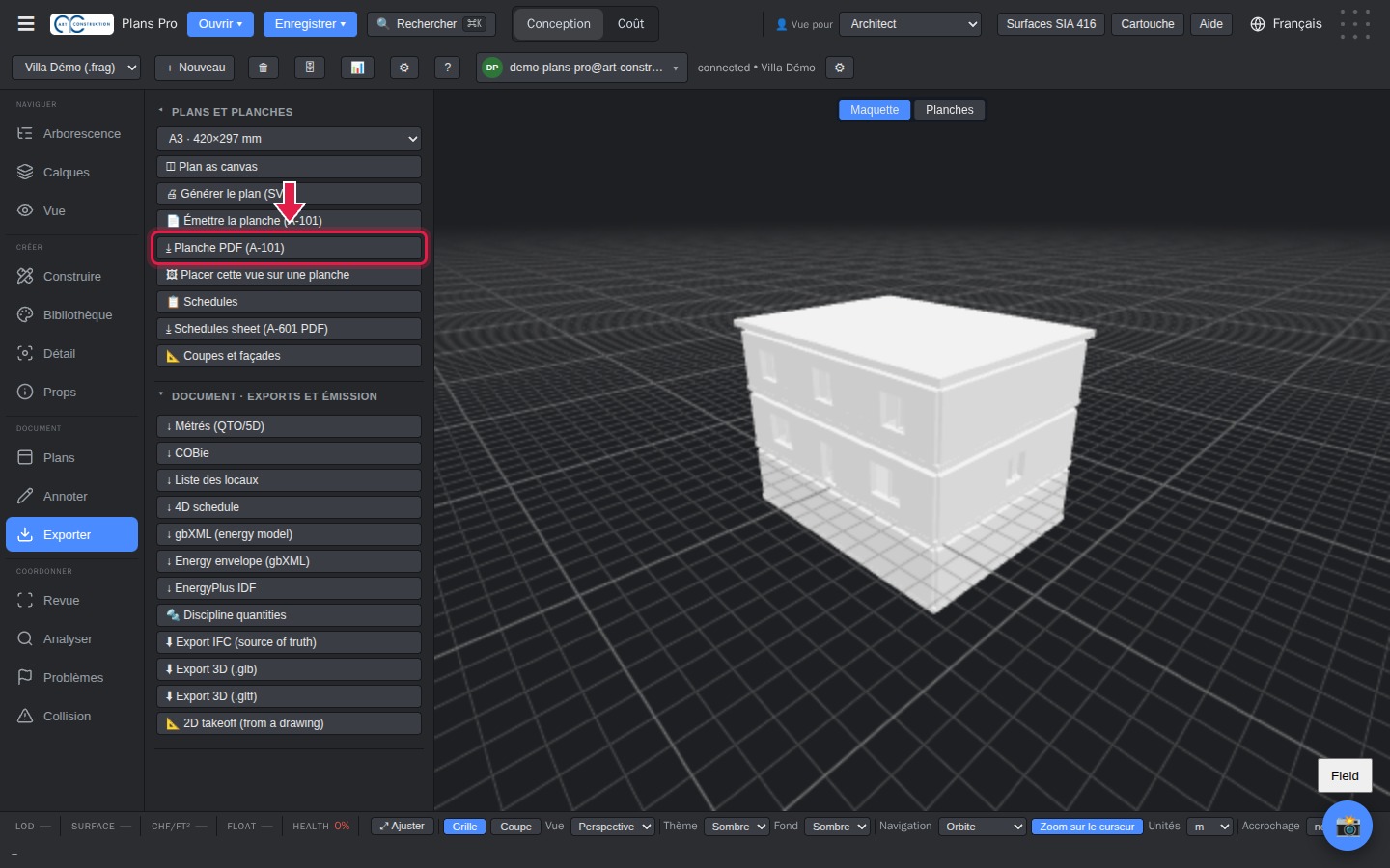
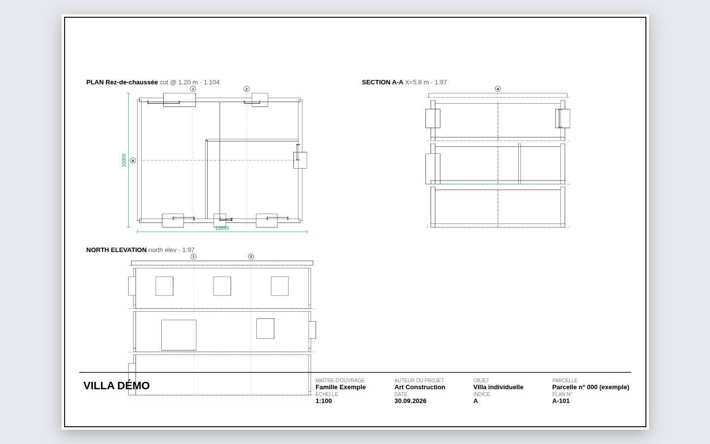
Click Planche PDF (A-101) (PDF sheet (A-101)). The sheet opens in a new tab, ready to print or save.
35The sheet with the Swiss title block
The title block is printed at the bottom of the sheet.
11. PDF, DXF and Excel exports
36Quantities in Excel
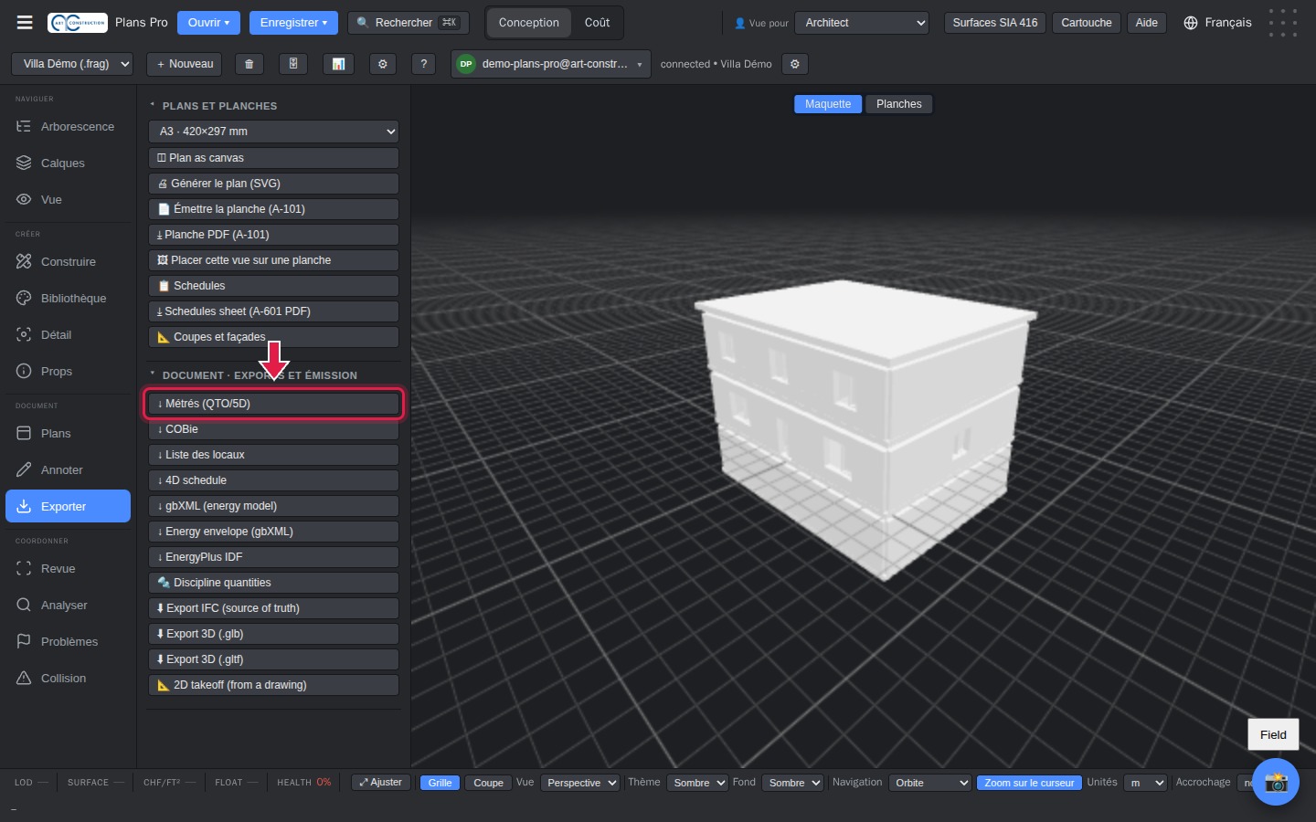
In Exporter (Export), expand “Document · Exports et émission” (Document · Exports and issue) and click Métrés (QTO/5D) (Quantities (QTO/5D)). You get an Excel file with the length, area and volume of each element, per level.
37Save the project
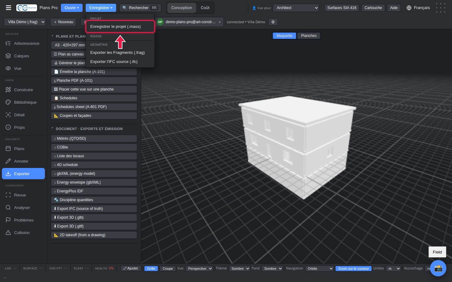
Your changes are saved automatically in Switzerland. To keep a full copy on your computer, click Enregistrer (Save) then Enregistrer le projet (.mass) (Save the project (.mass)).
Example files: A3 sheet (PDF) Quantities (Excel)
Part 2 – Work with an existing file
12. Open an existing IFC file
38Create a new project
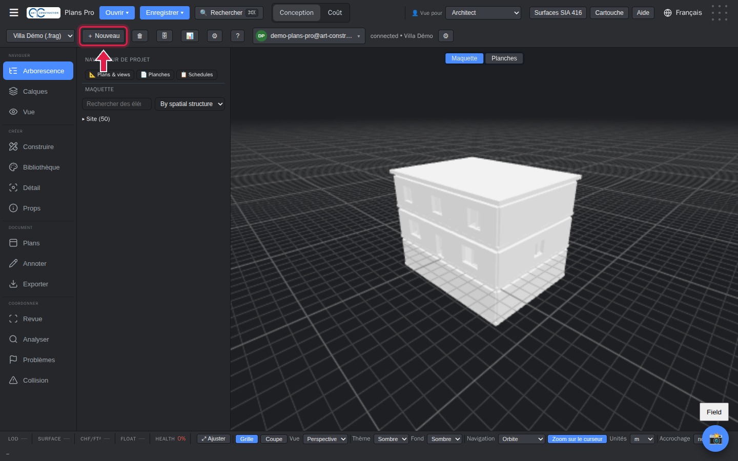
Click + Nouveau (New), at the top, to create an empty project.
39Name the project
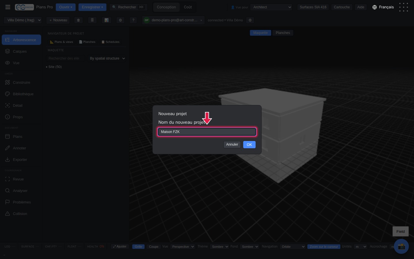
Type the project name, for example “Maison FZK”, then press Entrée.
40Open the IFC file
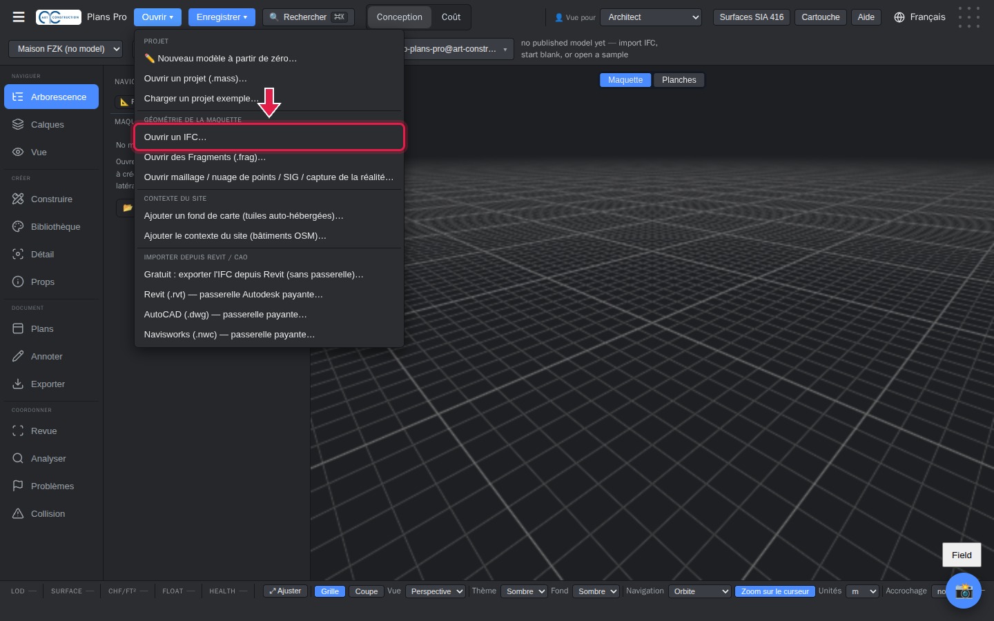
Click Ouvrir (Open), then Ouvrir un IFC… (Open an IFC…), and choose your file. Loading a large model may take a few minutes.
41The model is open
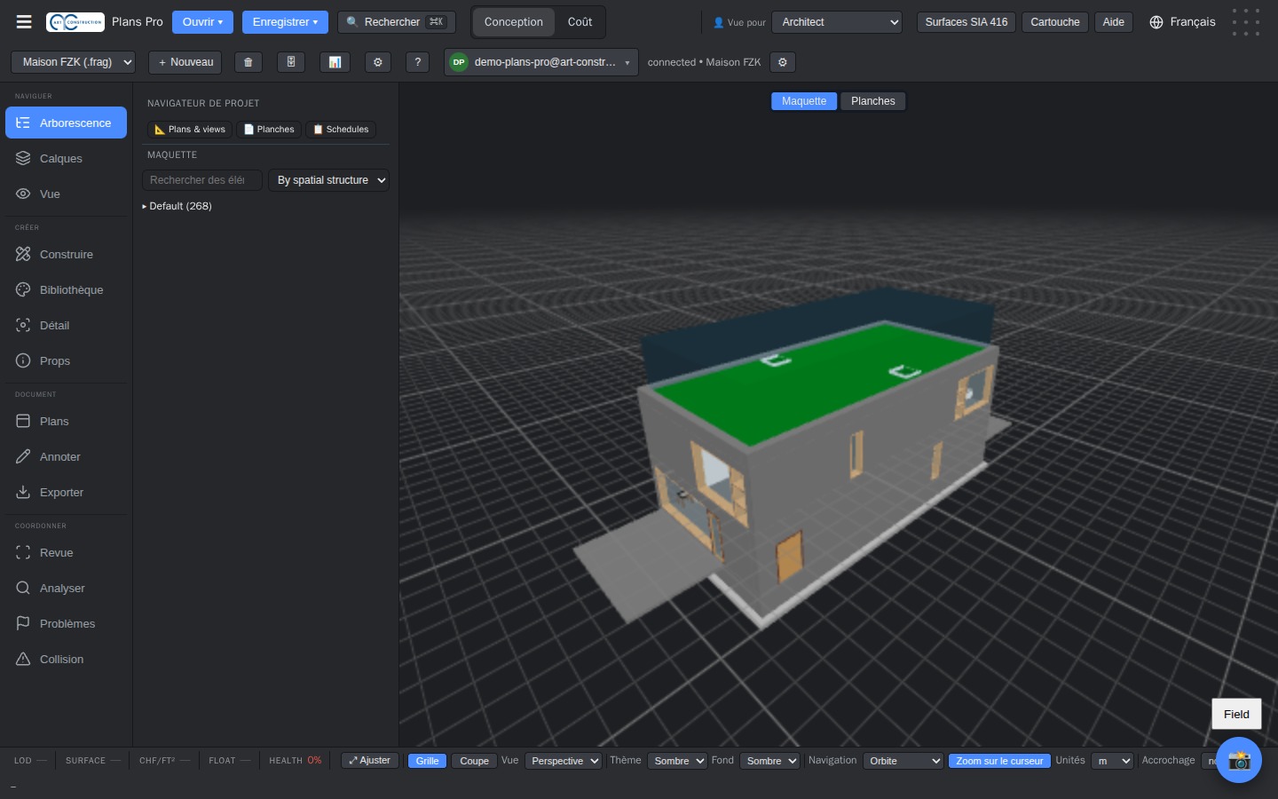
The model is displayed in 3D. You can then use all the tools in this guide: plans, sections, SIA 416 areas, exports.
42The model tree
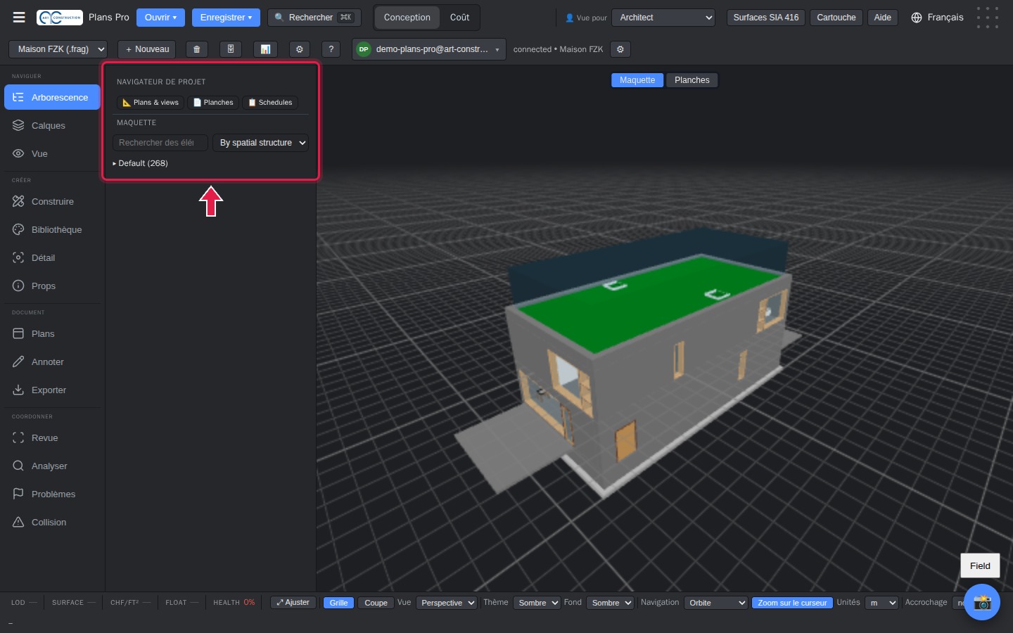
The Arborescence (Tree) panel lists the building, its levels and its elements. Click an element to find it in the model.
43Areas of an existing file
The Surfaces SIA 416 (SIA 416 areas) button reads the areas stored in the file. If the file does not contain the area of its rooms, the SN column stays empty: nothing is estimated.
Example file: “AC20-FZK-Haus.ifc” (FZK house), © Karlsruher Institut für Technologie (KIT), Institut für Automation und angewandte Informatik, licensed under CC BY 4.0.
13. Start from a 2D plan (DXF or image)
Plans Pro cannot yet automatically turn a DXF plan into 3D walls and rooms. However, you can place a scanned plan under the model and draw the walls on top of it.
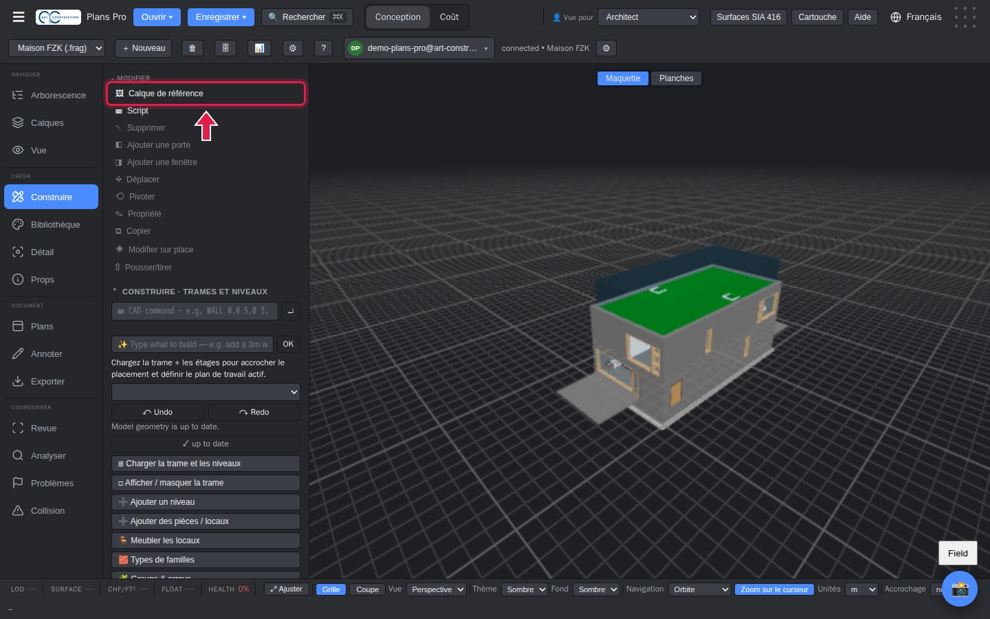
44Reference layer
In Construire (Build), click Calque de référence (Reference layer).
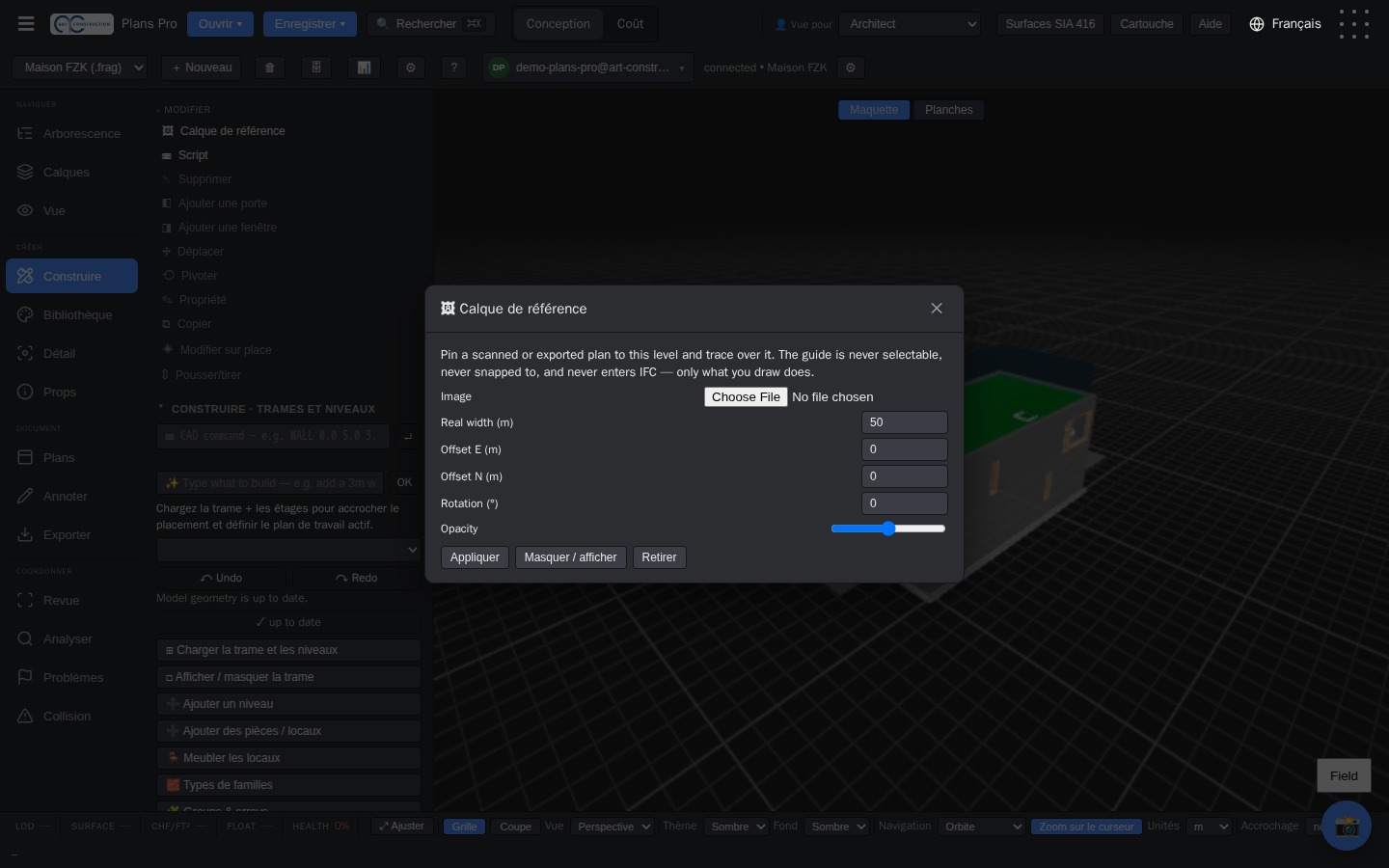
45Place the plan image
Choose the plan image (PNG or JPG), enter its real width in metres, then click Appliquer (Apply). Then draw the walls on top of it (chapter 3). For a DXF, first save it as an image from your CAD software.
14. Good to know
- Lengths are always entered in metres.
- Roofs are flat; pitched roofs are not available yet.
- Rooms are created automatically as a grid: there is no tool yet to draw a room by hand.
- Open an IFC file in a new project: in a project that is already open, it replaces the model.
- The title block is in French or German.
- Some secondary labels in Plans Pro are still in English.
A question? Send a request to support.