Excavation, slope and retaining wall guide
This guide shows, step by step, how to use the Excavation Studio: calculating volumes for a sloped excavation, dimensioning trench shoring and checking a reinforced concrete L-shaped retaining wall. The studio is free and works in your browser.
1. Getting started
1Locating screen areas
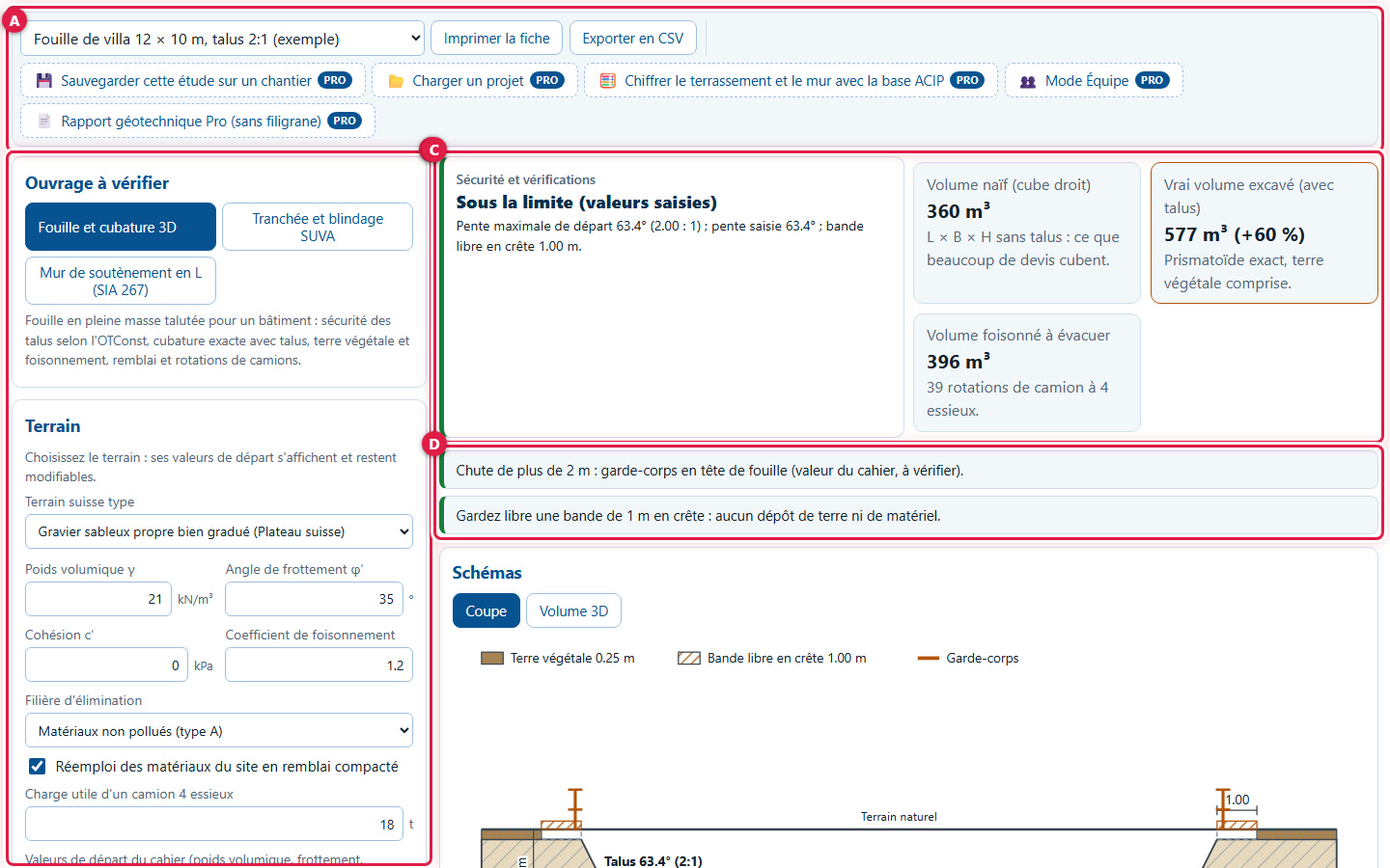
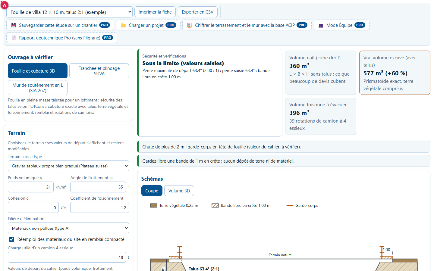
Everything takes place on a single page. (A) The top bar: the list of starting examples, Print sheet and Export to CSV. (B) On the left, your settings: the structure to be checked, the ground, then the dimensions. (C) On the right, the result cards. (D) Below, the construction site messages. Further down: the diagrams, three detail tabs, the legal disclaimer and the assumptions.
Everything is calculated in your browser. Nothing is sent or saved: if you close or reload the page, your work will disappear. Print or export before leaving.
2Choosing a starting example
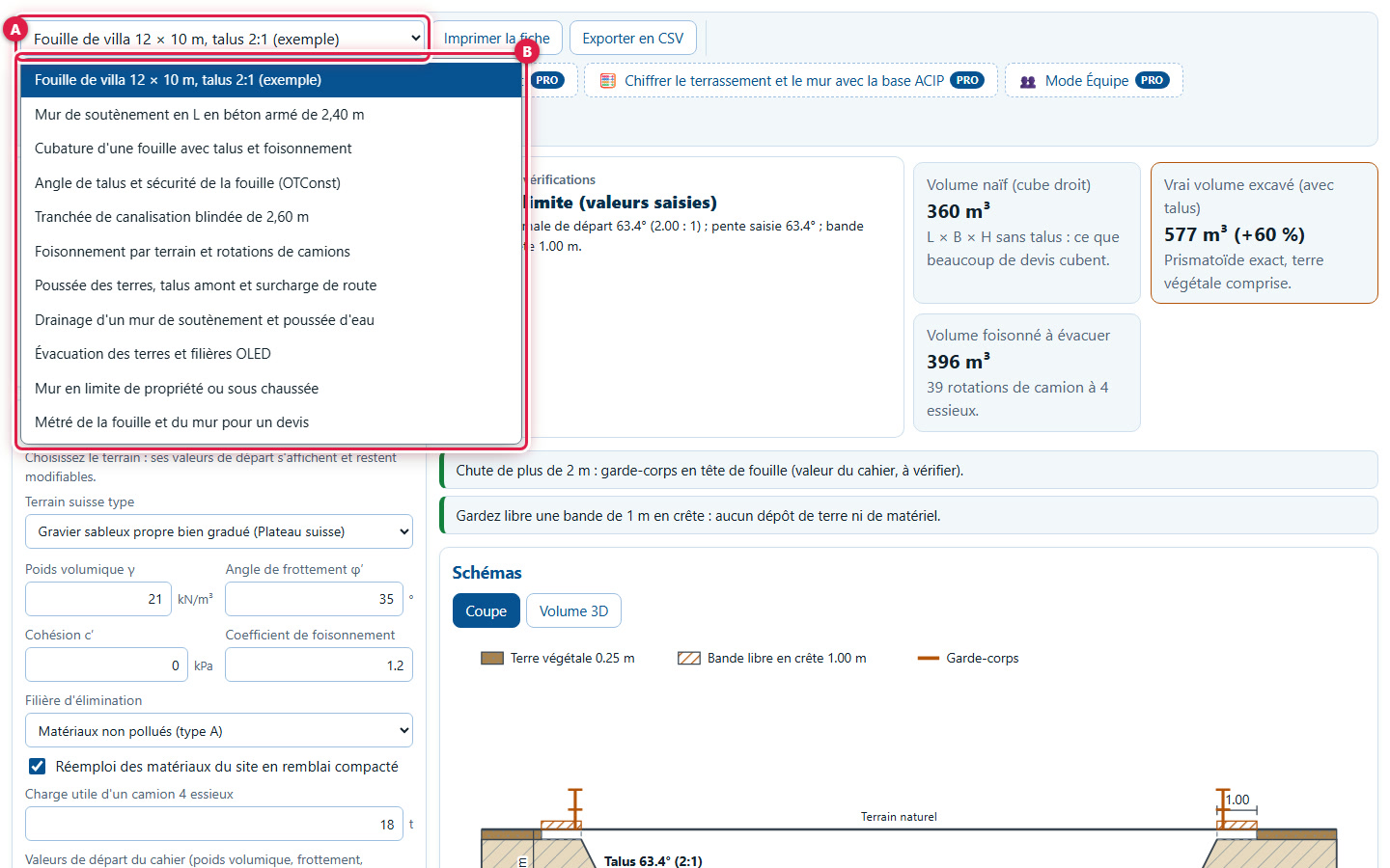
The list (A) offers 11 examples (B): a villa excavation, an L-wall, a shored trench, ground comparisons, a property boundary wall, a quantity takeoff for a quote… Each choice loads the structure, ground and dimensions of the example.
When you change examples, your inputs are replaced by those of the new example.
3Choose the structure to check
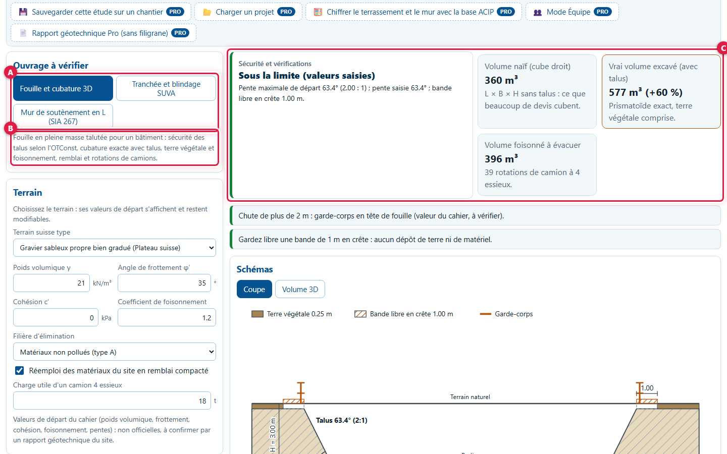
Three buttons (A): Excavation and 3D volume, Trench and SUVA shoring and L-shaped retaining wall (SIA 267). A sentence (B) describes what the chosen structure does. The result cards (C) change accordingly: status and volumes for the excavation, trench box and pressure for the trench, overturning, sliding and bearing capacity ratios for the wall.
4Set the ground
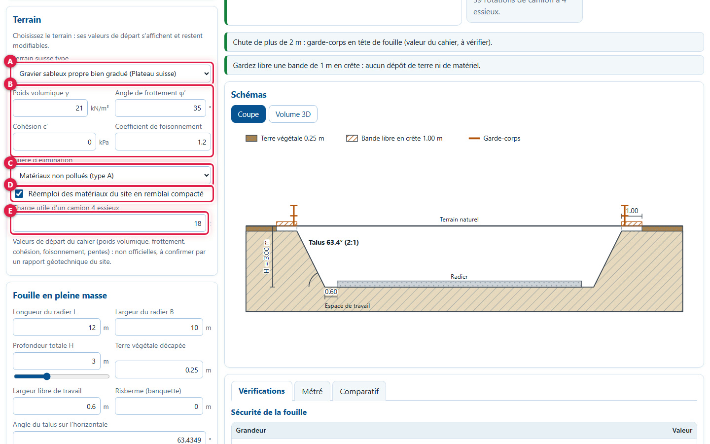
The Soil panel starts with (A) the list of standard Swiss soils. The four values (B) (unit weight γ, friction angle φ′, cohesion c′, swell factor) are filled with the starting values of the chosen soil: you can modify them. (C) The soil disposal pathway, (D) the reuse of site materials as backfill and (E) the payload of a 4-axle lorry (18 t by default) are used for cubature.
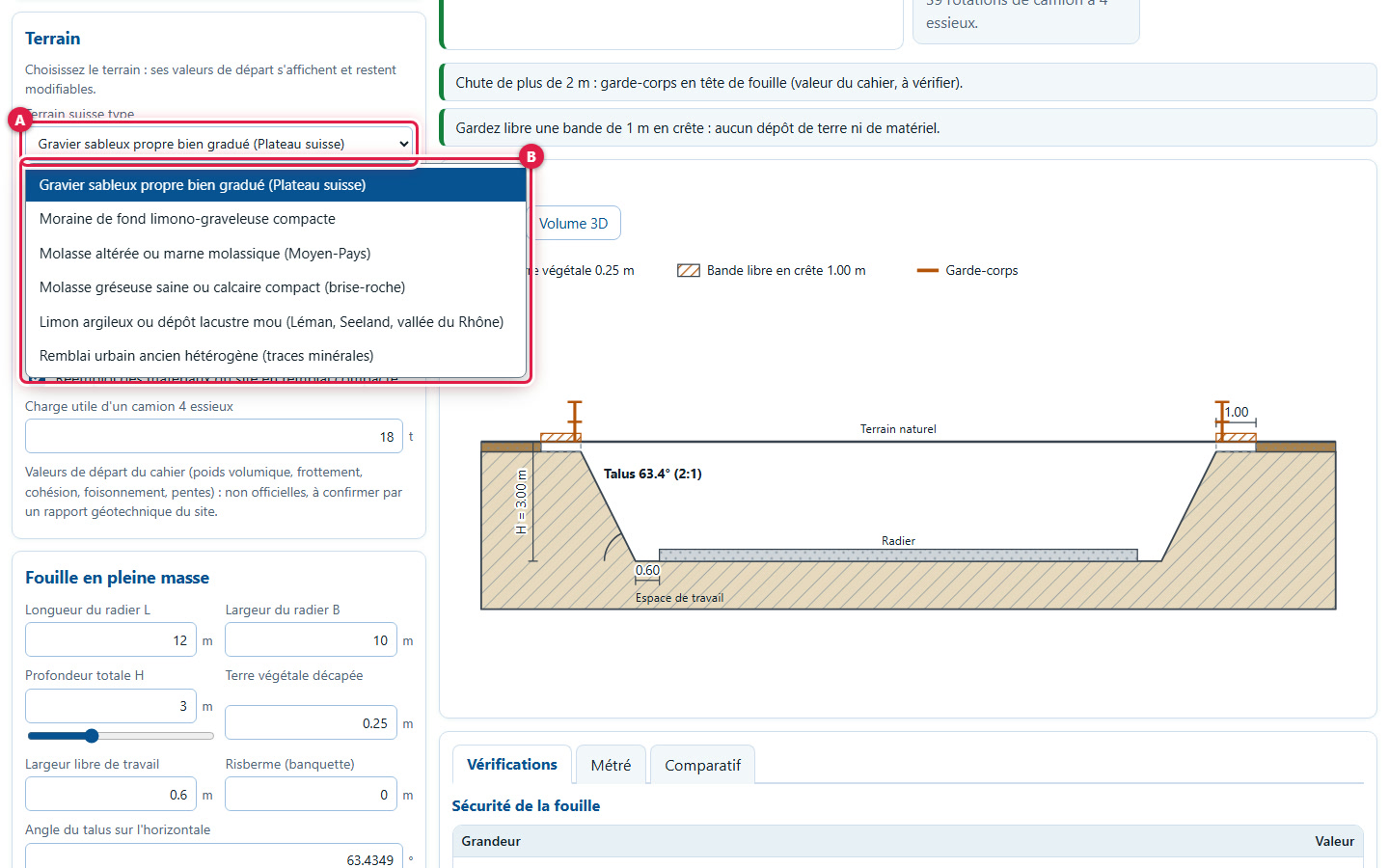
5Choose one of the standard soils
The list (A) contains the 6 standard Swiss soils (B), from sandy gravel of the Swiss Plateau to old urban fill. Changing the soil replaces the four values and resets the slope angle to the maximum starting slope of that soil.
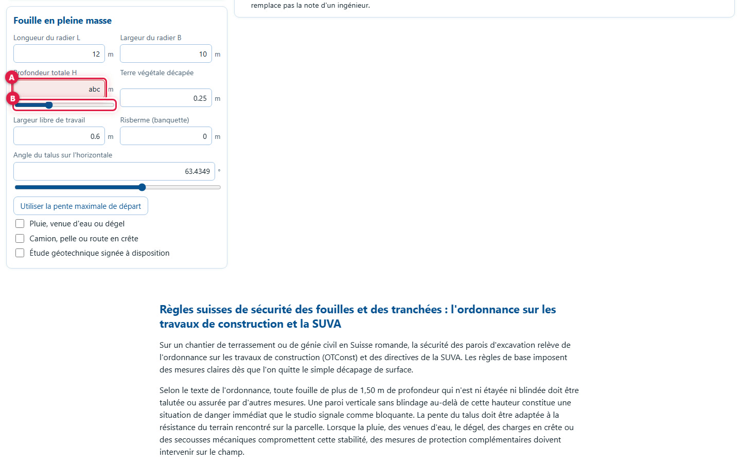
6Enter a value
Each dimension is entered in a field (A); some also have a slider (B) (depth, slope angle). Results are recalculated on every keystroke. An empty or unreadable value, like "abc" here, is marked in red in the field.
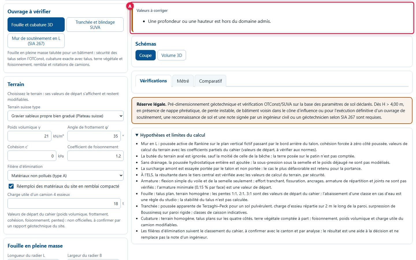
7Read the correction message
As long as a value is invalid, card (A) displays « Values to be corrected » with the reason, and the diagrams and tables remain empty. The studio never replaces an invalid value with zero: correct the field and the results come back.
2. Sloped excavation and 3D earthwork
8Read the safety verdict
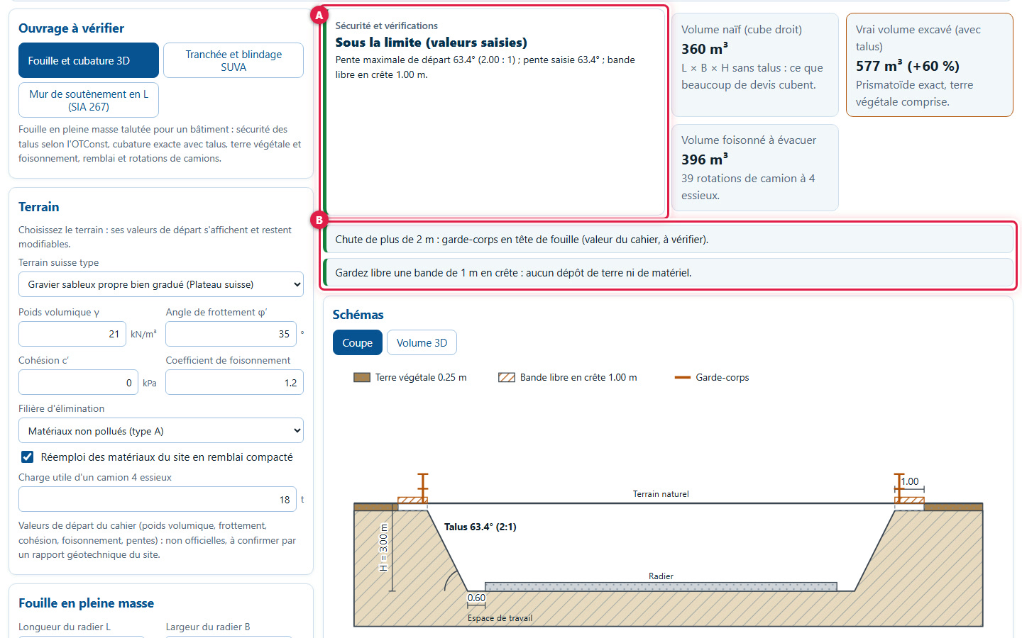
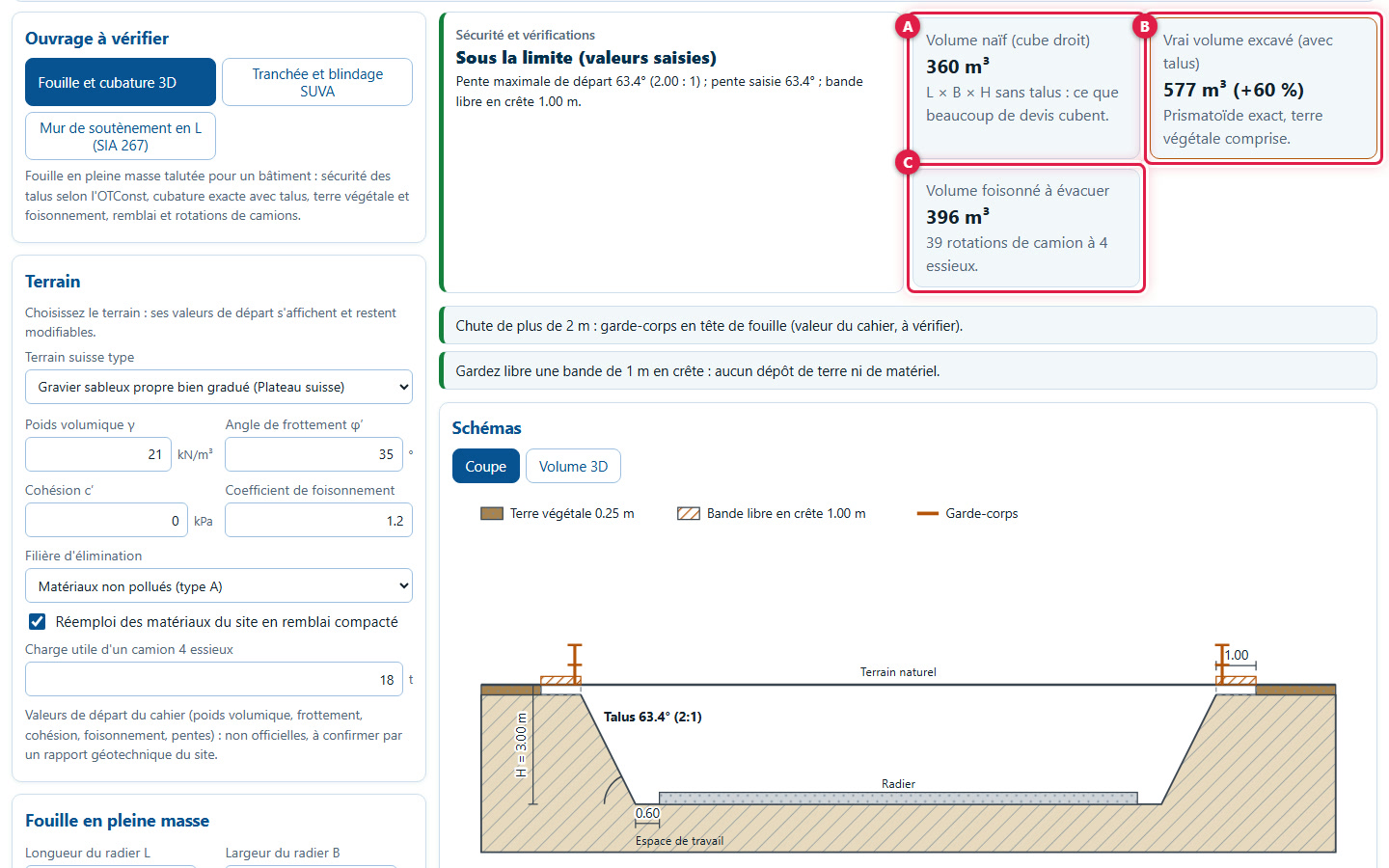
Choose Excavation and 3D volume. Card (A) gives the status: Below limit (entered values) for the 12 × 10 m villa excavation. It recalls the maximum initial ground slope (63.4°, i.e. 2.00 : 1), the entered slope (63.4°) and the clear strip to keep at the top (1.00 m). (B) Construction site messages follow: edge protection at the top of the excavation, clear strip at the top.
There are three statuses: Below limit (entered values), Warning to resolve and Blocking: must be corrected.
9Read the three volumes
Three volumes. (A) The naive volume as a right prism (360 m³): length × width × height, without slopes. (B) The true excavated volume with slopes, including topsoil (577 m³, i.e. 60 % more). (C) The bulking volume to be removed (396 m³ with a bulking factor of 1.2), i.e. 39 4-axle truckloads.
10Adjust the excavation
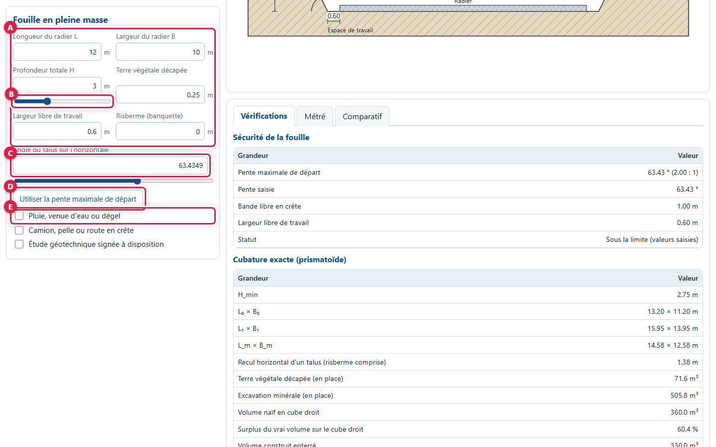
The Mass excavation panel: (A) length and width of the base slab, total depth, stripped topsoil, clear working width and berm (shelf). At the start: 12 × 10 m, depth 3 m, topsoil 0.25 m, working width 0.6 m. (B) The depth slider. (C) The slope angle to the horizontal, with its slider. (D) The Use the starting maximum slope button enters the maximum initial terrain slope in the field. (E) Three checkboxes: rain, water inflow or thaw; truck, excavator or road at the crest; signed geotechnical study available.
11Viewing an overly steep slope
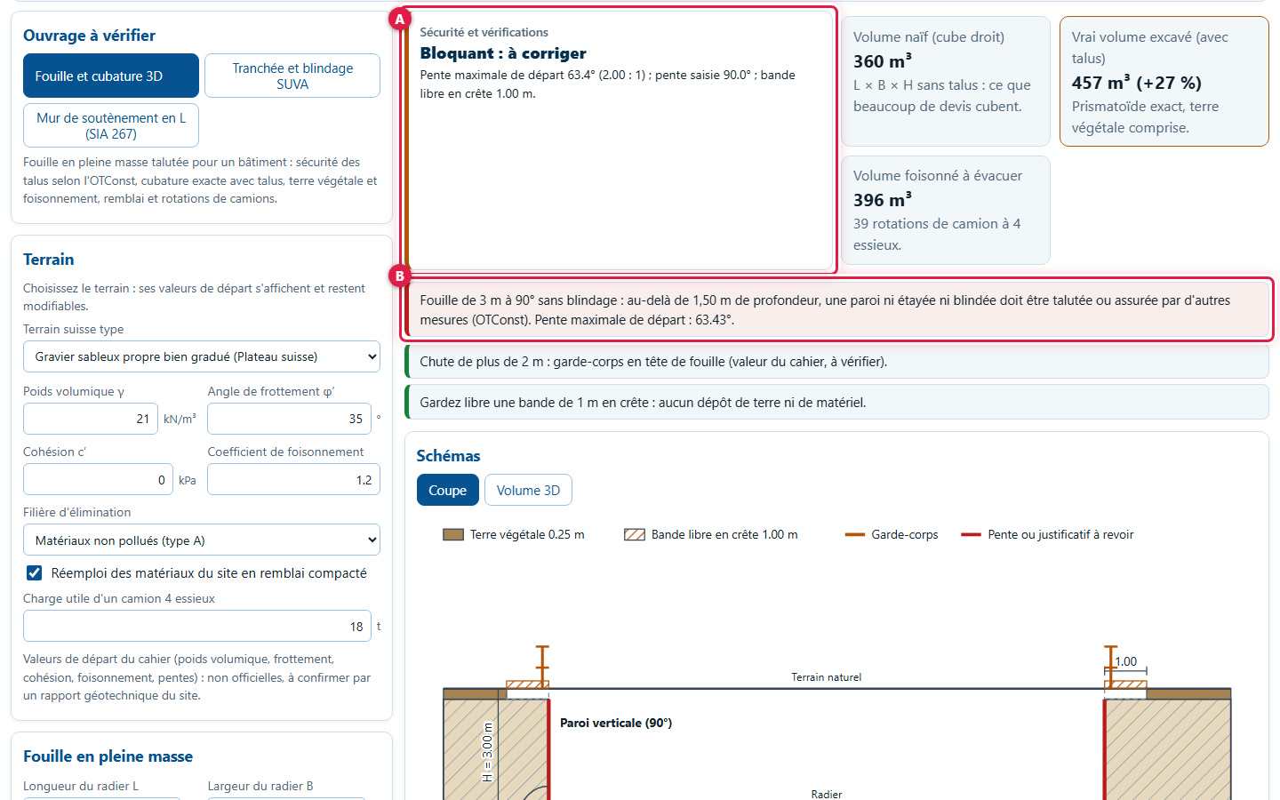
Set the angle to 90° (vertical wall) for the 3 m excavation. Card (A) switches to Blocking: must be corrected and a red message (B) explains: beyond 1.50 m in depth, an unsupported or unbraced wall must be sloped or secured by other measures (OTConst). The volume decreases (457 m³), but the wall is unsafe without shoring: the studio blocks it.
12Lifting a block with the maximum slope
Check Rain, water inflow or thaw: the maximum initial terrain slope is lowered by one class and the entered slope, now too steep, is flagged. Click Use the starting maximum slope: the field takes the maximum slope and the status changes. In the video, this is done on the villa excavation in sandy gravel.
13Check rain, surcharge or study
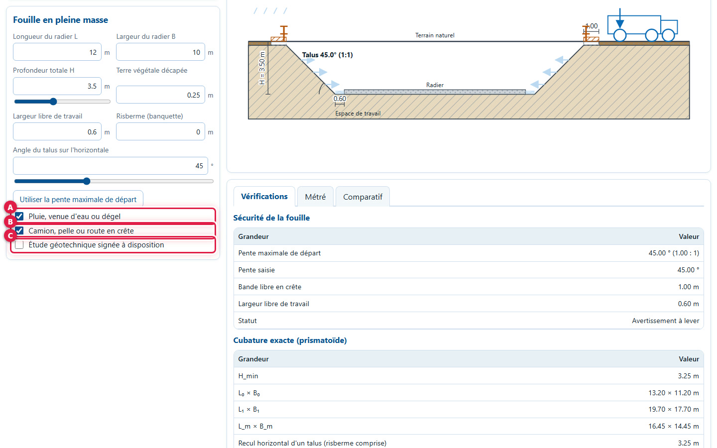
Three checkboxes change the checks. (A) Rain, water inflow or thaw: the maximum initial slope is lowered by one class. (B) Truck, excavator or road at the crest: an additional surcharge is counted and the clear strip at the crest is at least 1.00 m. (C) Signed geotechnical study available: the studio notes this and reminds you to attach it to the file; it does not replace it. The "Slope angle and excavation safety (OTConst)" example checks the first two, with moraine and 3.5 m depth.
14Reading water and surcharge messages
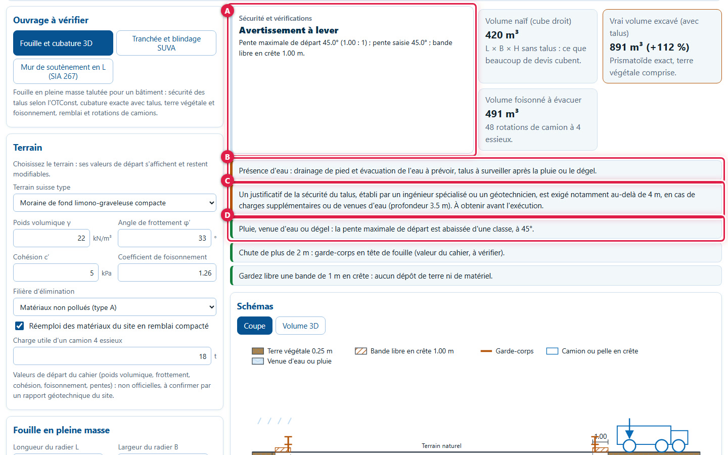
With water and surcharge checked, card (A) displays Warning to resolve and the maximum initial slope drops to 45.0°. Three messages: (B) toe drainage to be planned and slope to be monitored; (C) justification of slope safety, prepared by a specialised engineer or geotechnical engineer, is required notably beyond 4 m, in the event of additional surcharges or water inflows; (D) the maximum slope is lowered by one class.
15View the 3D volume
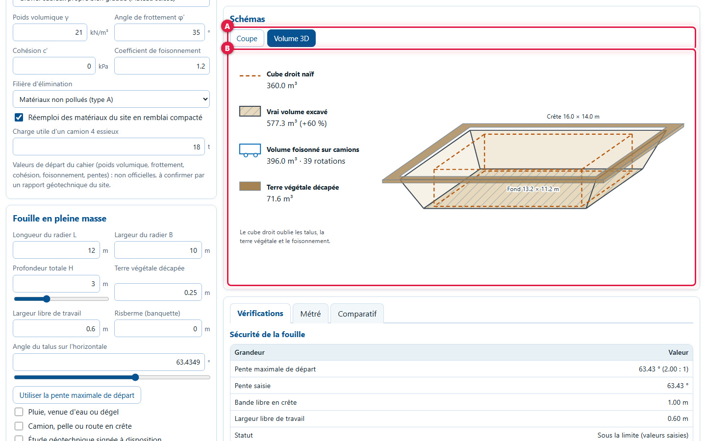
The excavation cross-section (default) shows the topsoil, the slope, the free strip at the crest, the guardrail and the working space. In Diagrams, button (A) 3D volume replaces it with a perspective view (B): the naive right-angled dashed cube, the true excavated volume, the bulked volume on trucks and the stripped topsoil, with their volumes. Section switches back to the cross-section.
16Read the verifications
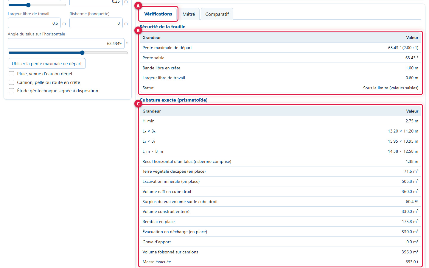
Below the diagrams, tab (A) Verifications provides two tables: (B) excavation safety (maximum initial slope, entered slope, free strip at the crest, free working width, status) and (C) exact cubature by prismoid: dimensions, slope setback, topsoil, mineral excavation, buried constructed volume, backfill, disposal, imported gravel, bulked volume, disposed mass and truck rotations.
17Compare the six sites
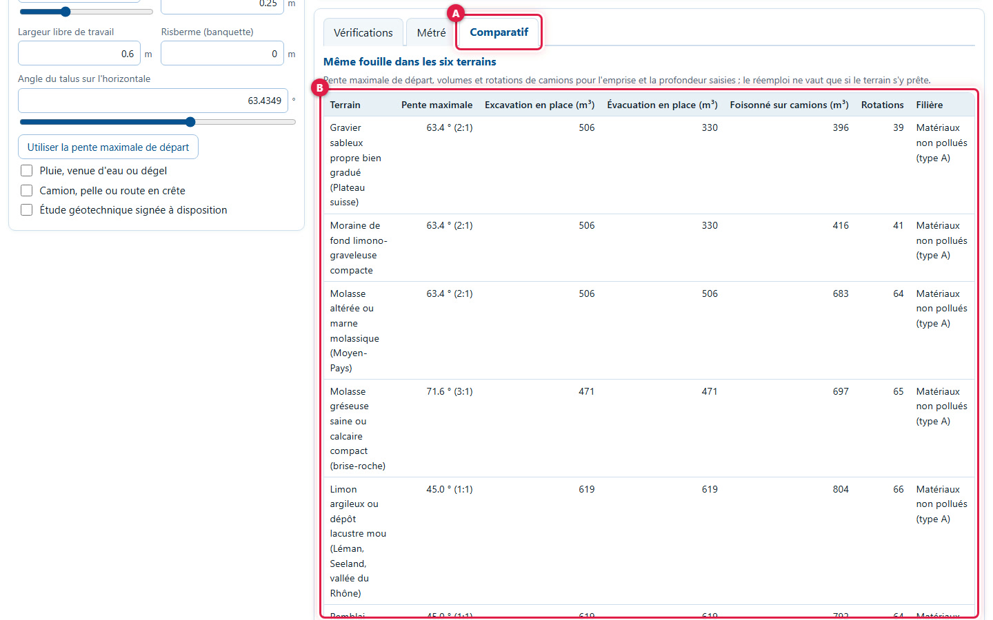
Tab (A) Comparison recalculates the same excavation across the 6 soils (B): maximum initial slope, in-situ excavation, in-situ disposal, bulked volume on trucks, rotations and disposal pathway. Material reuse only applies if the soil is suitable. This is the "Bulking by soil type and truck rotations" example.
18Read the pathways and slopes by class
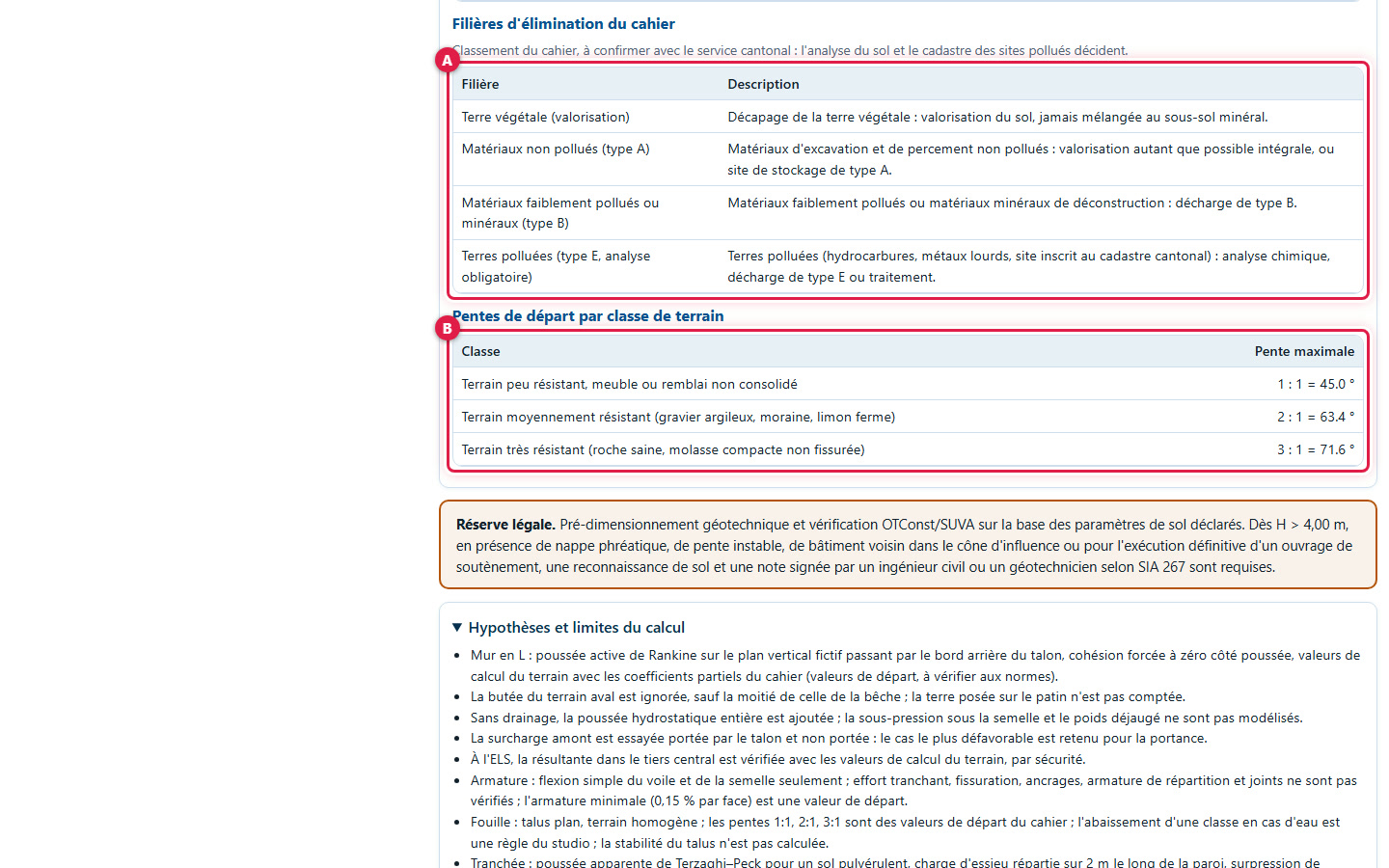
The bottom of the same tab contains (A) the 4 disposal pathways from the workbook (topsoil, unpolluted type A materials, slightly polluted or mineral type B materials, polluted type E soils) and (B) the initial slopes by soil class (3 classes: 1:1, 2:1 and 3:1). In the "Soil disposal and OMoD channels" example, old urban backfill is classified as type B.
3. Braced trench
19Read the four maps
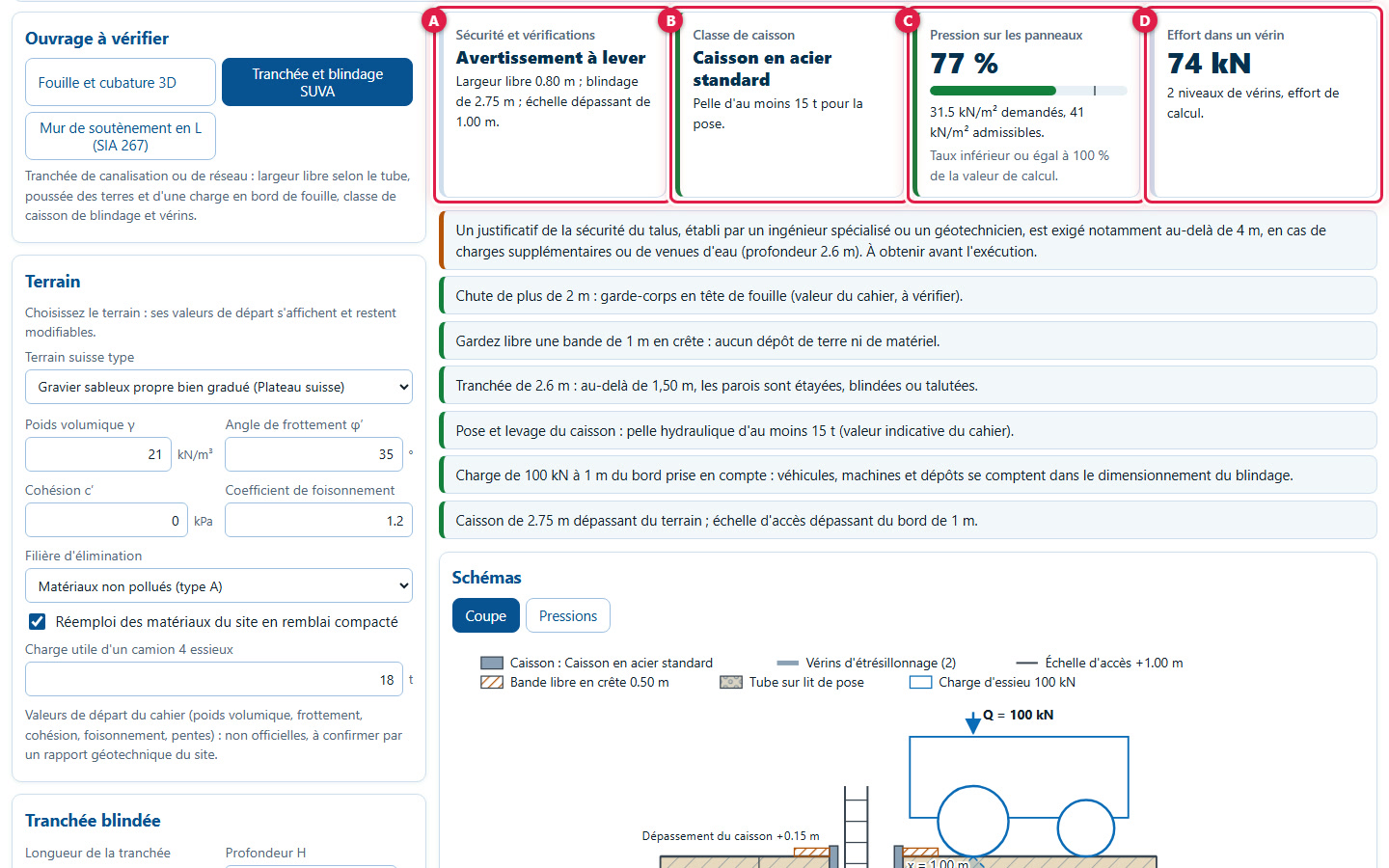
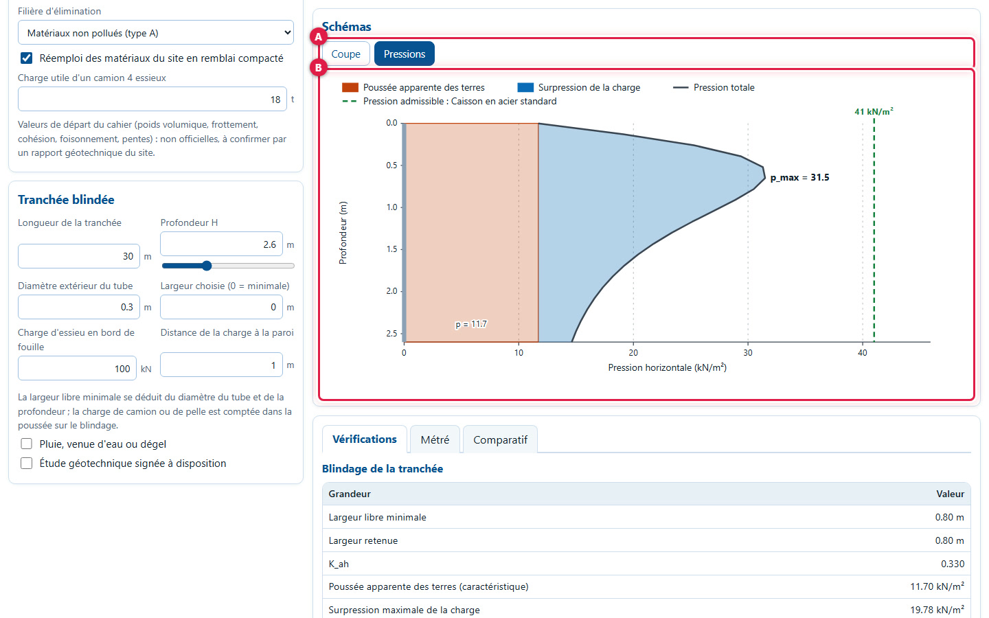
Select Trench and SUVA shoring (example "2.60 m shored utility trench"). (A) The status, with the clear width (0.80 m), the trench shoring height (2.75 m) and the access ladder extending past the edge (1.00 m). (B) The selected trench box class and the excavator required to install it (at least 15 t). (C) The pressure on the panels: 77 %, i.e. 31.5 kN/m² requested for 41 kN/m² allowable, with a gauge. (D) The design force in a strut (74 kN, 2 strut levels).
20Adjust the trench
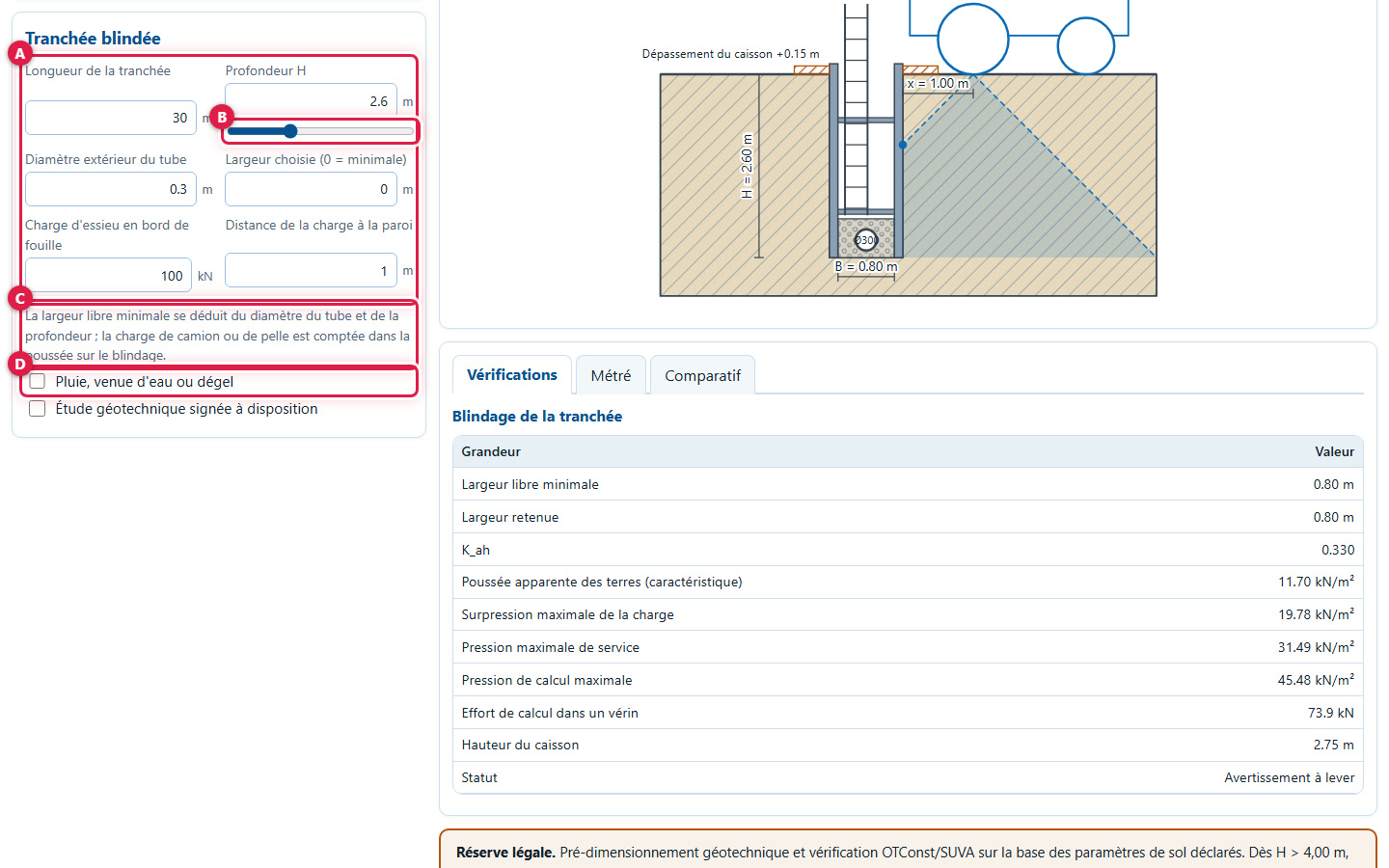
The panel Sheet-piled trench: (A) trench length, depth H, outer diameter of the pipe, chosen width (0 = minimum), axle load at the edge of the excavation (100 kN initially) and distance from the load to the wall (1 m). (B) The depth slider. (C) The minimum clear width is deduced from the pipe diameter and depth; the load of a lorry or an excavator is included in the shoring pressure. (D) Rain, water inflow or thaw, and signed geotechnical report.
21Read the trench section
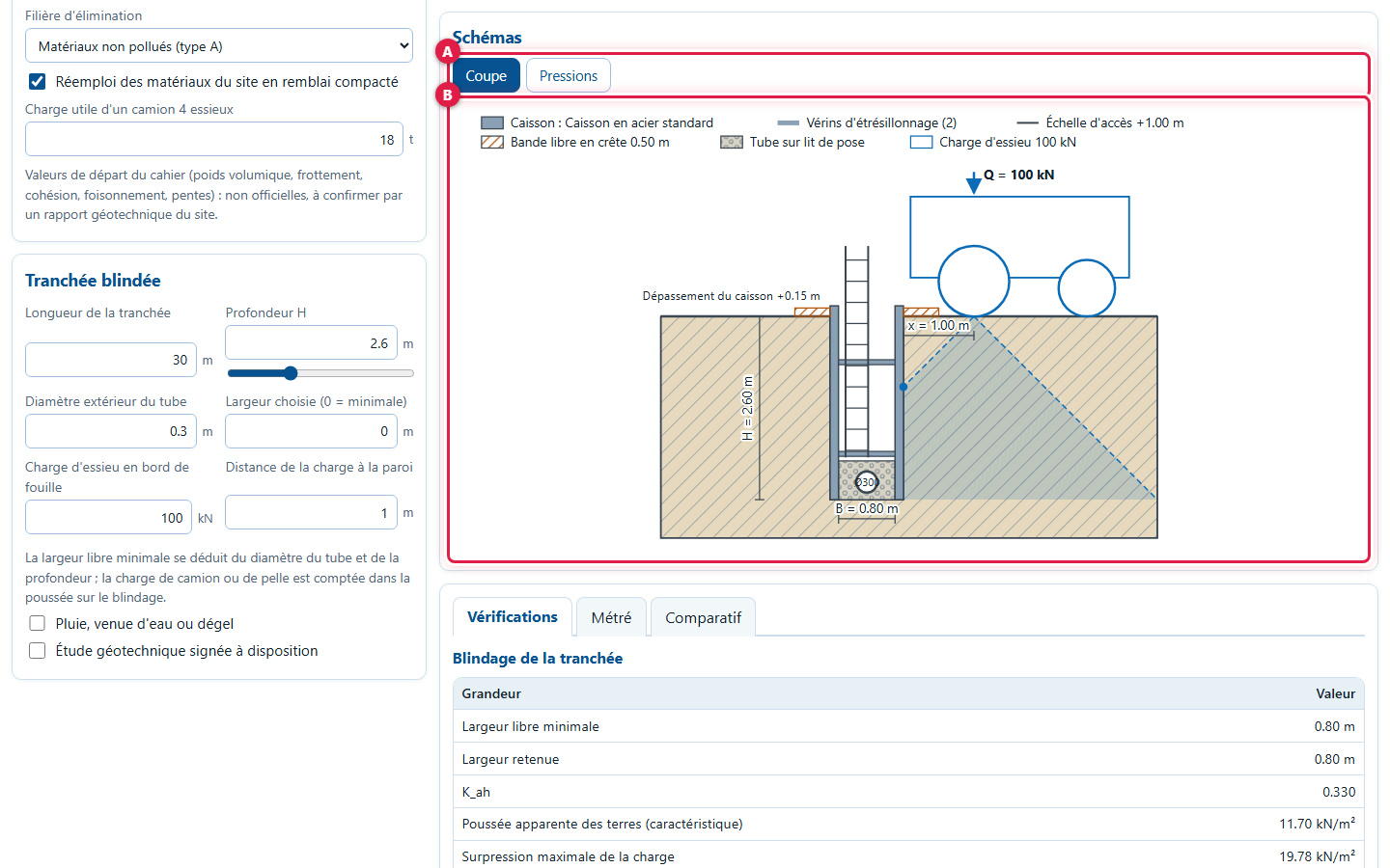
(A) The view Section (B) draws the trench box, the shoring struts, the access ladder, the pipe on its bedding, the clear strip at the top and the axle load with its distance to the wall.
22Read the pressures
The button (A) Pressures shows (B) the horizontal pressure as a function of depth: apparent earth pressure, surcharge pressure, total pressure and allowable trench box pressure (green dashed line).
23Increase the depth
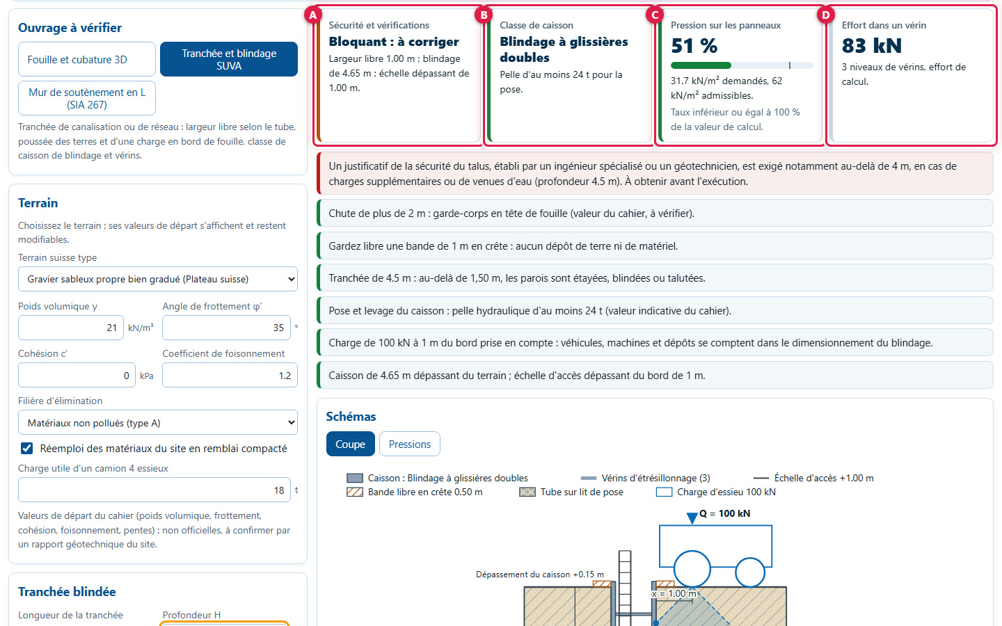
Drag the depth slider or type 4.5: the trench box class changes to Slide rail shoring system (B) with an excavator of at least 24 t, the requested pressure drops to 51 % of the allowable one (C) and 3 strut levels are required (D). Status (A) is Blocking: must be corrected: beyond 4 m, the safety verification becomes a red message.
24Load too high: out of catalogue
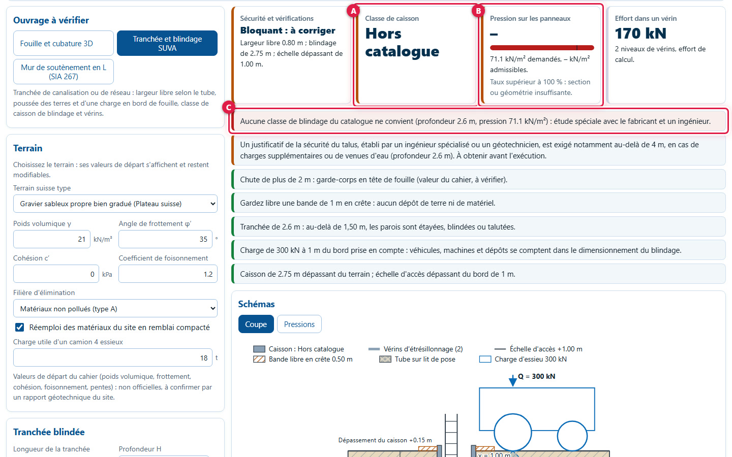
With an axle load of 300 kN at 1 m from the edge, the required pressure rises to 71.1 kN/m². Card (A) reads "Out of catalogue", card (B) displays no allowable pressure and a red message (C) requests a special study with the manufacturer and an engineer.
25Compare trench box classes
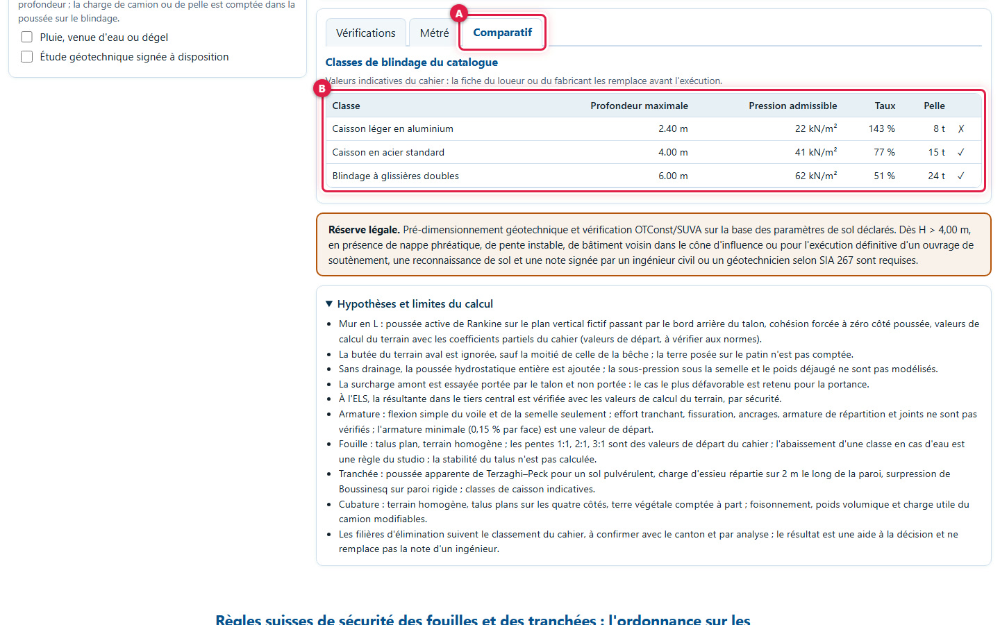
In the tab (A) Comparison, the table (B) compares the 3 classes from the catalogue: maximum depth, permissible pressure, rate, excavator, and a checkmark ✓ or a cross ✗ indicating whether the class is suitable. These are indicative values from the studio manual, without manufacturer names: the rental company or manufacturer datasheet replaces them prior to execution.
4. L-shaped retaining wall
26Read the five cards
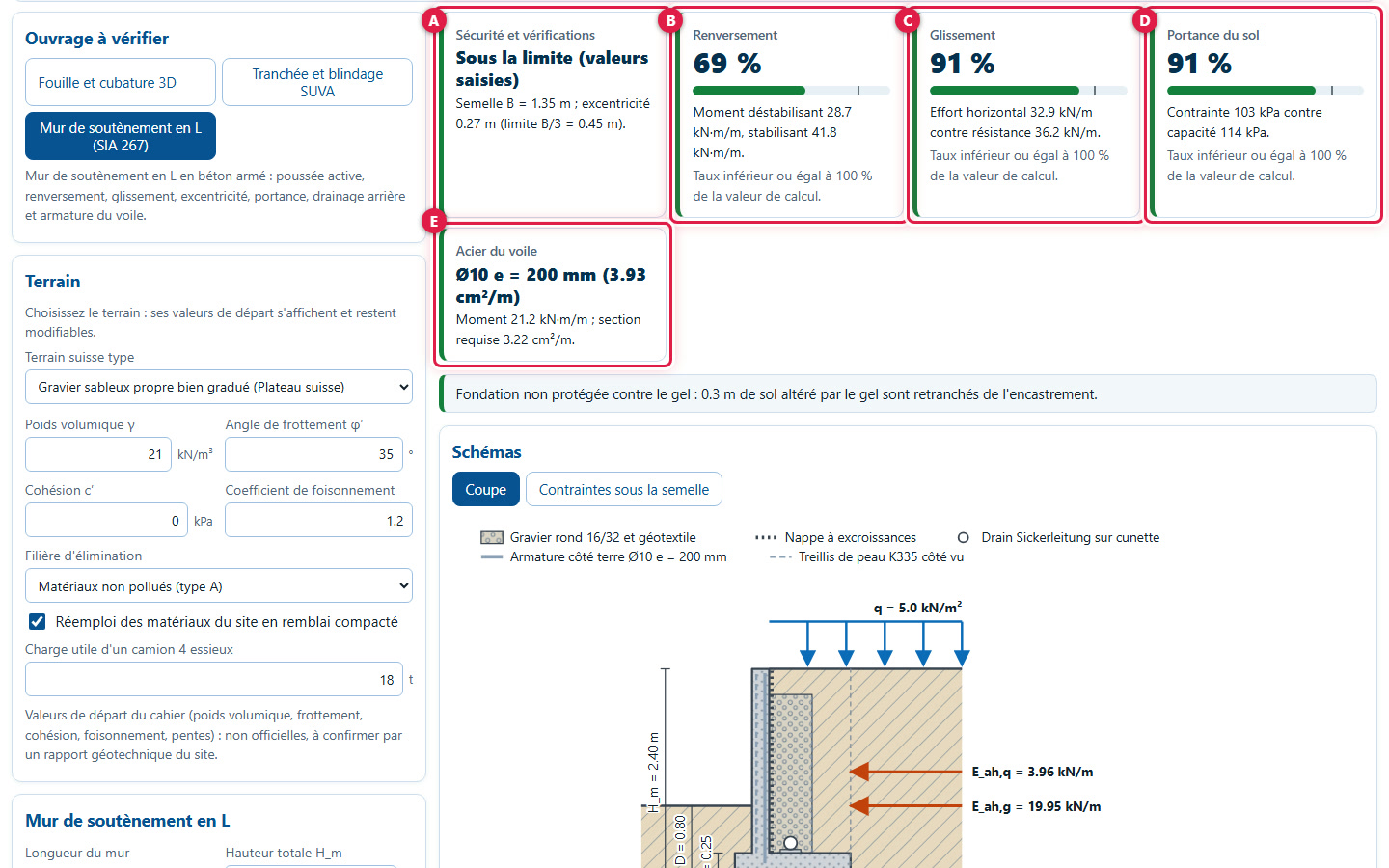
Choose L-shaped retaining wall (SIA 267) (example "2.40 m reinforced concrete L-shaped retaining wall"). (A) Status, with base width (1.35 m) and eccentricity (0.27 m for a B/3 limit = 0.45 m). (B) Overturning: 69 %. (C) Sliding: 91 %. (D) Bearing capacity: 91 %. (E) Stem reinforcement: Ø10 e = 200 mm (3.93 cm²/m). Each ratio is compared to 100% of the design value, using a gauge.
27Adjust wall geometry
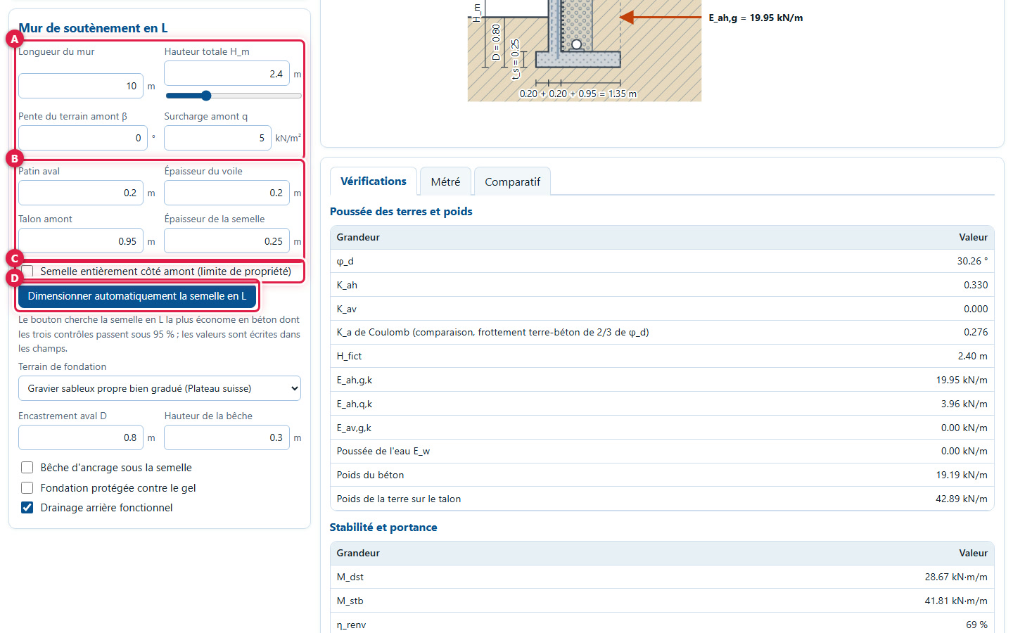
The L-shaped retaining wall panel: (A) wall length, total height H_m, backfill slope β and backfill surcharge q (10 m, 2.4 m, 0° and 5 kN/m² initially). (B) Toe, stem thickness, heel and base thickness (0.2, 0.2, 0.95 and 0.25 m). (C) The base box entirely on the backfill side (property boundary). (D) The Automatically size the L-shaped footing button.
28A wall that is too high: ratios exceed 100 %
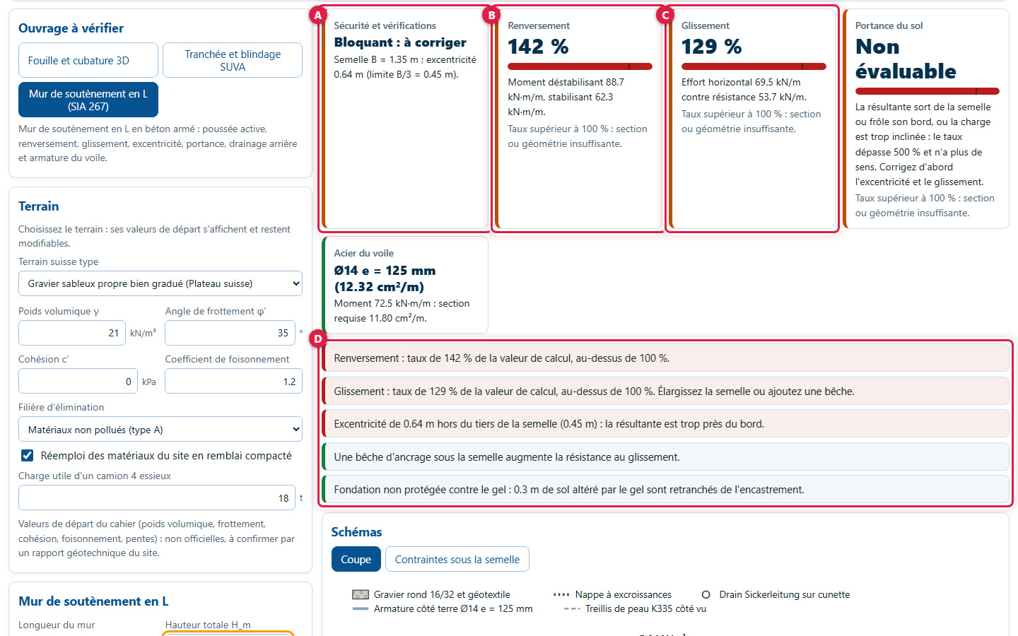
Increase the height to 3.6 m without changing the base. The status (A) changes to Blocking: must be corrected; overturning (B) reaches 142 % and sliding (C) 129 %. (D) The red messages state what to correct: overturning, sliding ("widen the base or add a shear key") and eccentricity of 0.64 m, outside the middle third of the base (0.45 m).
29Dimension the base automatically
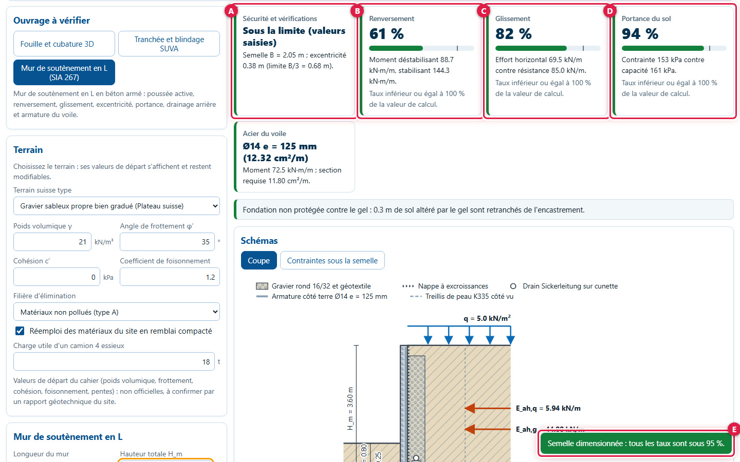
Click on Automatically size the L-shaped footing. The studio searches for the most concrete-efficient L-shaped base whose three checks fall below 95 % and writes the values into the fields: here, a base of 2.05 m with a backfill heel of 1.65 m. Cards (A), (B), (C) and (D) turn green again: overturning 61 %, sliding 82 %, bearing capacity 94 %. (E) A message confirms this.
30Adjusting the foundation, shear key, frost and drainage
(A) The foundation soil is chosen from the same list as the soil. (B) The toe embedment depth D (0.8 m) and the shear key height (0.3 m). Three boxes: (C) an anchor shear key under the base, which increases sliding resistance; (D) foundation protected against frost (otherwise, a frost-affected soil thickness is subtracted from the embedment depth); (E) functional rear drainage, checked by default.
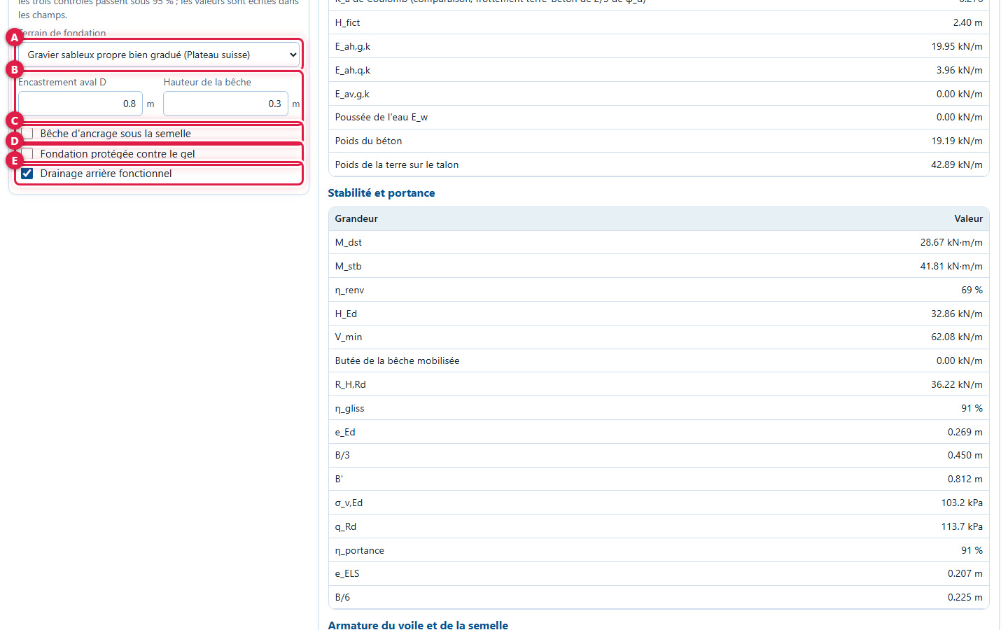
31Reading the wall cross-section
(A) The Section view (B) draws the L-shaped wall to scale with the surcharge q, rounded gravel and its geotextile, dimpled membrane, drain on swale, earth-side reinforcement, thrusts E_ah,g and E_ah,q and base dimensions.
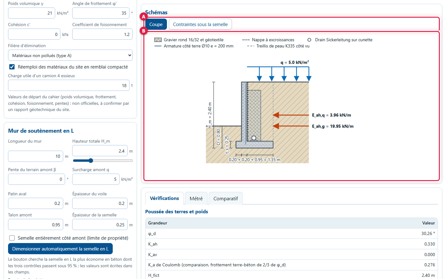
32Read the stresses beneath the base
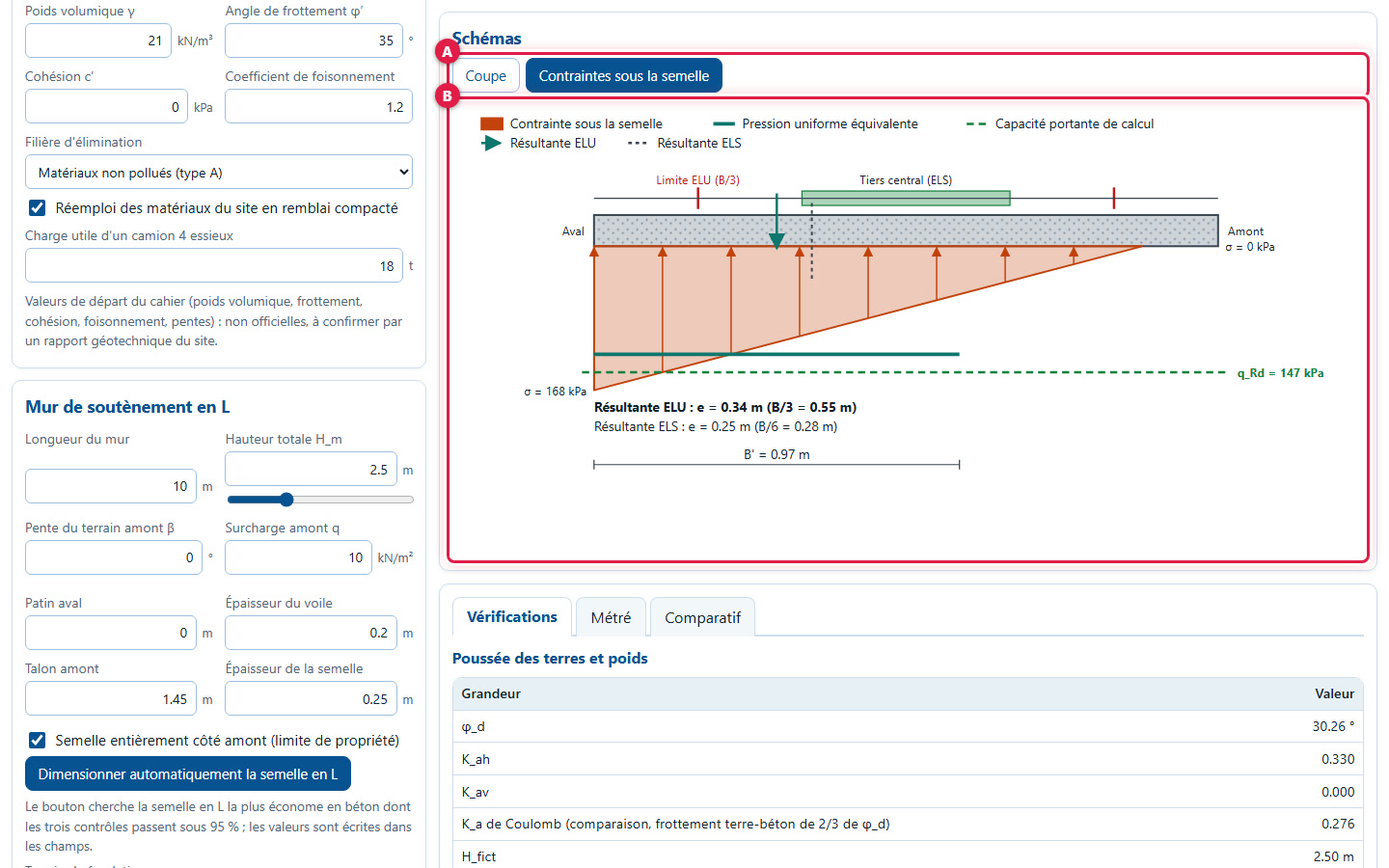
Button (A) Subgrade stresses shows (B) the trapezoid of soil stresses beneath the base, the resultant at the ultimate limit state with the middle-third limit (B/3), the resultant in service within the middle third, the equivalent uniform pressure, and the design bearing capacity. Here: a wall with the base entirely on the uphill side (example "Property boundary or under-road wall").
33Read the earth pressure
In (A) Verifications, the table (B) "Earth pressure and weight" gives the design friction angle φ_d, the earth pressure coefficients K_ah and K_av, a Coulomb coefficient for comparison, the fictitious height, the earth and surcharge pressures, the water pressure, the weight of the concrete, and the weight of the soil on the heel.
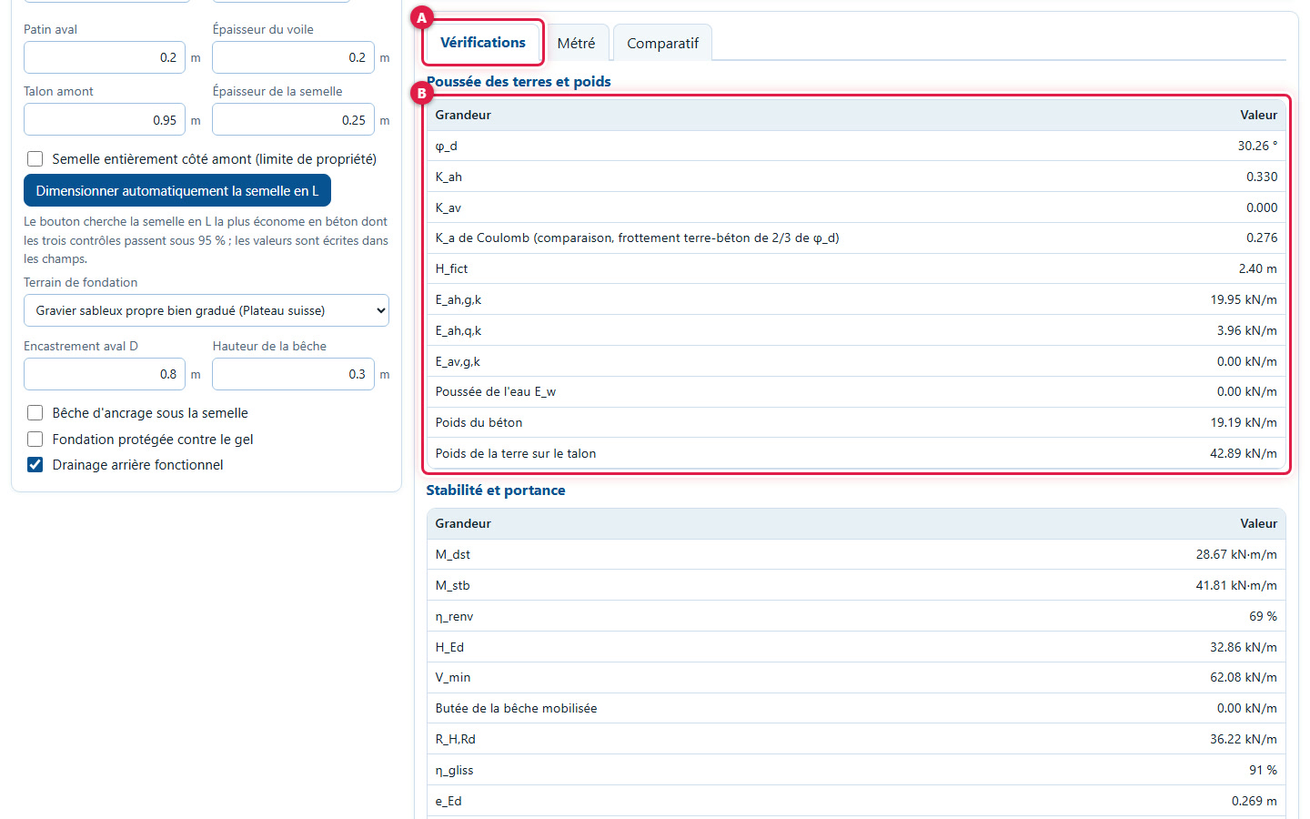
34Read stability and bearing capacity
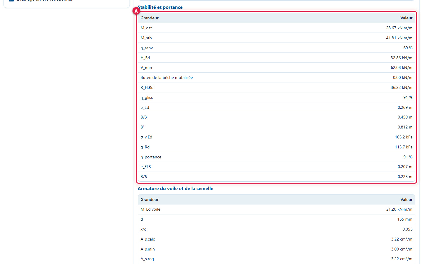
Table (A) "Stability and bearing capacity" details the destabilising and stabilising moments with the overturning ratio, the horizontal force and sliding resistance, the eccentricity to be compared with B/3, the stress beneath the base against the bearing capacity, and the service eccentricity to be compared with B/6.
35Read the reinforcement
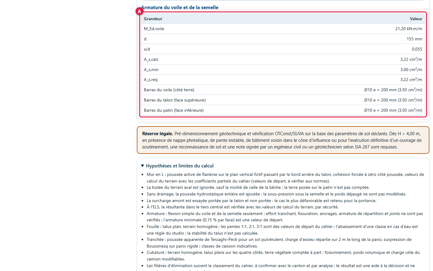
Table (A) "Stem and footing reinforcement" gives the bending moment in the stem (21.2 kN·m/m), the effective depth, the calculated area, the minimum area, and the required area (3.22 cm²/m), followed by the selected bars for the stem, the heel, and the toe.
36Compare with and without drainage
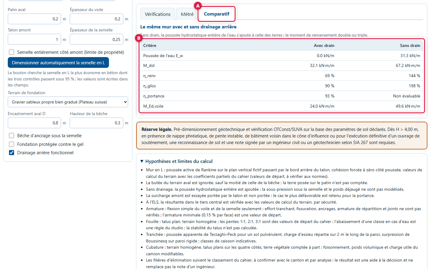
The (A) Comparison tab recalculates the same wall with and without rear drainage (B): water pressure, destabilising moment, overturning, sliding and bearing capacity ratios, and bending moment in the stem. Without a drain, the full hydrostatic pressure is added to the earth pressure. This is the « Retaining wall drainage and water pressure » example.
37Uncheck drainage
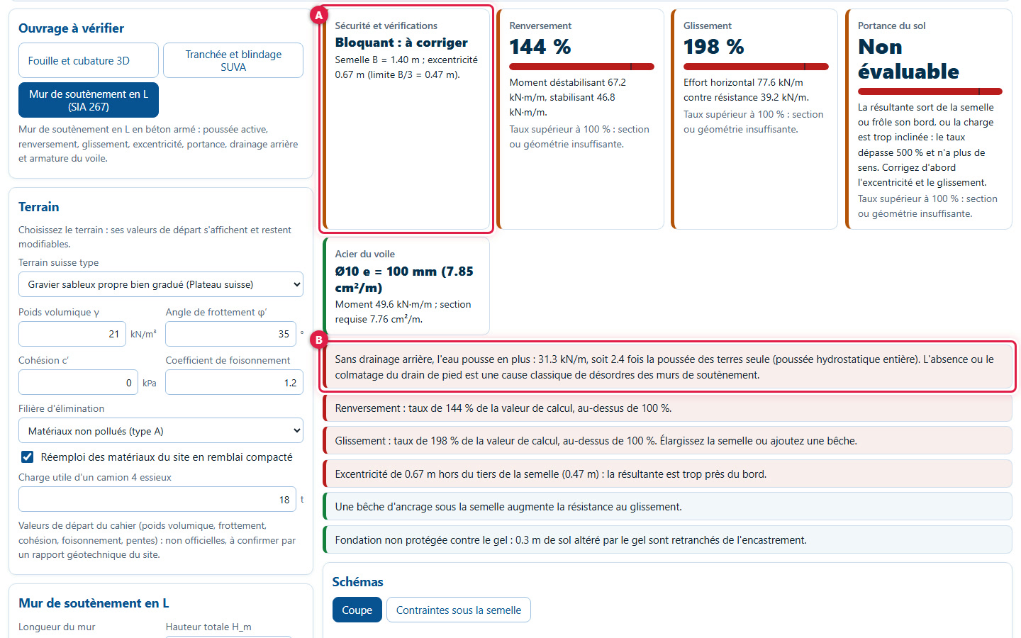
Uncheck Functional rear drainage: status (A) changes to Blocking: must be corrected and a red message (B) quantifies the water: 31.3 kN/m, which is 2.4 times the earth pressure alone. Overturning rises to 144 % and sliding to 198 %.
38Placing a wall at the property boundary
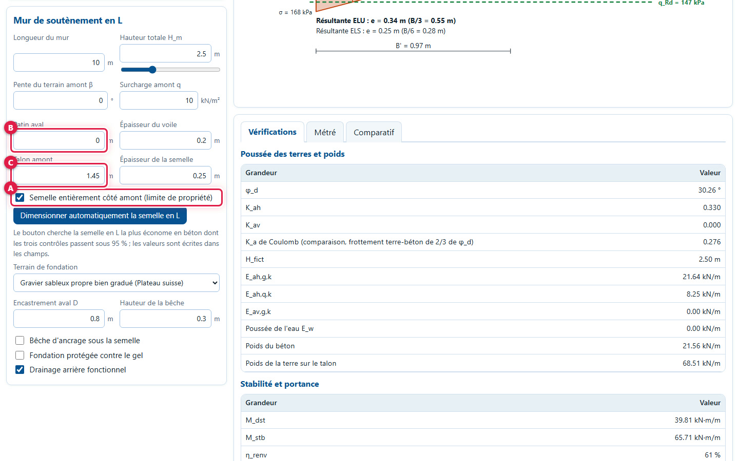
Check (A) the box for the base entirely on the upslope side: the downstream toe (B) becomes 0 m, and the upstream heel (C) widens (1.45 m in the « Property boundary or under-road wall » example). Automatic sizing respects this choice.
39Adding an upslope slope and a surcharge
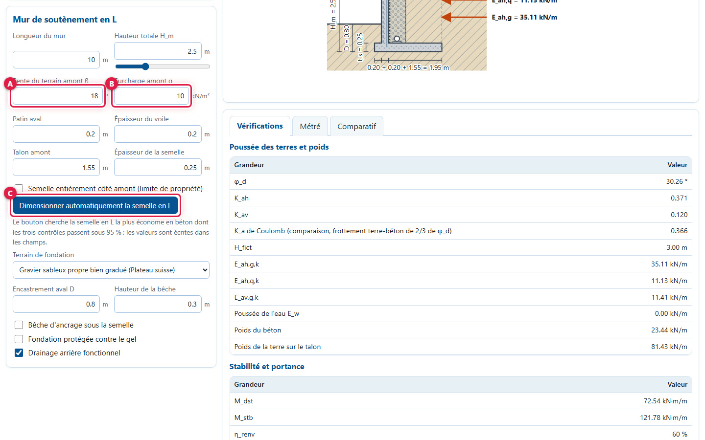
For sloping ground above the wall, enter the upslope angle β (A); for a road or storage area, enter the surcharge q (B). Example « Earth pressure, upstream slope and road surcharge »: β = 18° and q = 10 kN/m²; automatic sizing (C) gives a base width of 1.95 m (overturning 60 %, sliding 94 %, bearing capacity 84 %). If β reaches the design friction angle, the pressure can no longer be calculated and the studio indicates this.
5. Bill of quantities, printed sheet and export
40Read the bill of quantities
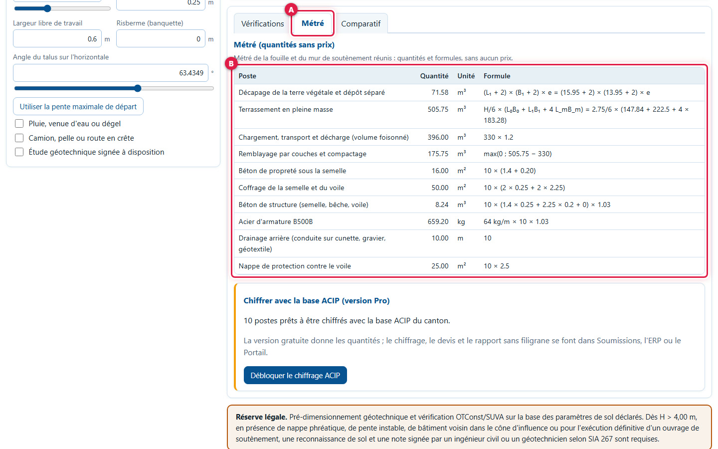
The (A) Bill of quantities tab lists (B) the work items with their quantity, unit and calculation formula: topsoil stripping, excavation, disposal, backfilling, blinding concrete, formwork, concrete, steel, drainage, protection membrane... For the combined excavation and wall (example "Excavation and wall quantities for a quote"), the table has 10 items. There are no prices.
41Pricing with the ACIP database
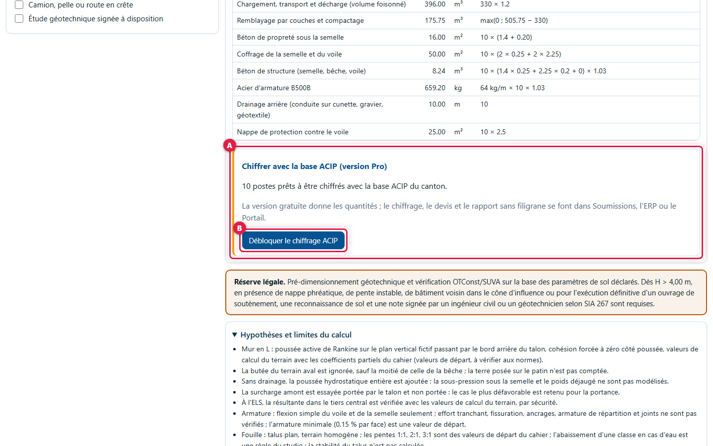
Below the table, block (A) shows the number of items ready to be priced using the ACIP database. Button (B) Unlock ACIP pricing opens an information window (see the last chapter). The free version provides the quantities; pricing, the quote and the report without watermark are done elsewhere, in Tenders, the ERP or the Portal.
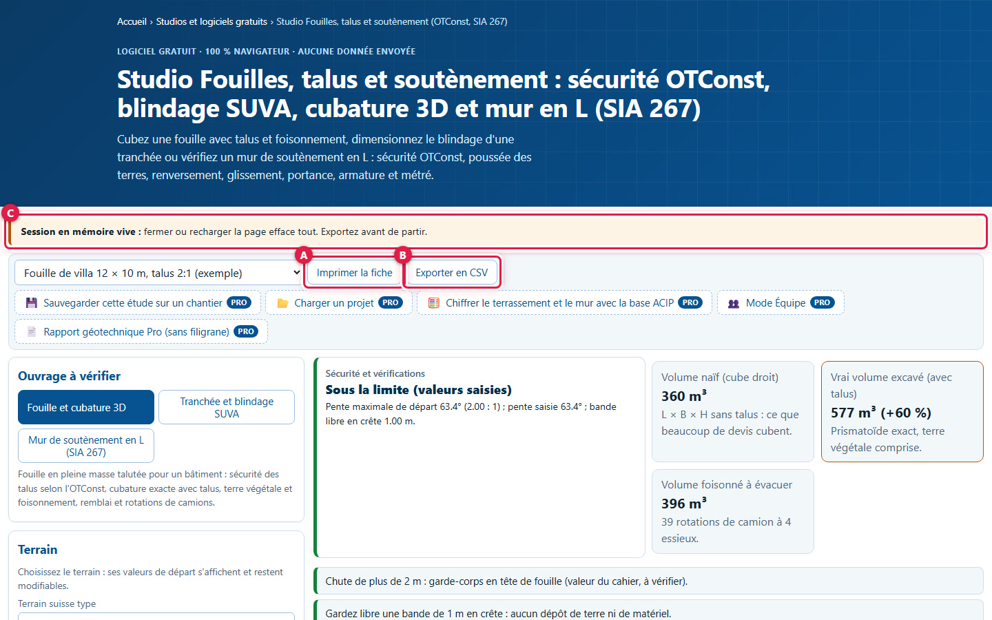
42Print or export
In the top bar: (A) Print sheet opens the browser print function with the pre-dimensioning sheet, and (B) Export to CSV downloads a CSV file (semicolon separator). (C) The reminder "session in RAM": nothing is saved, export before closing the page.
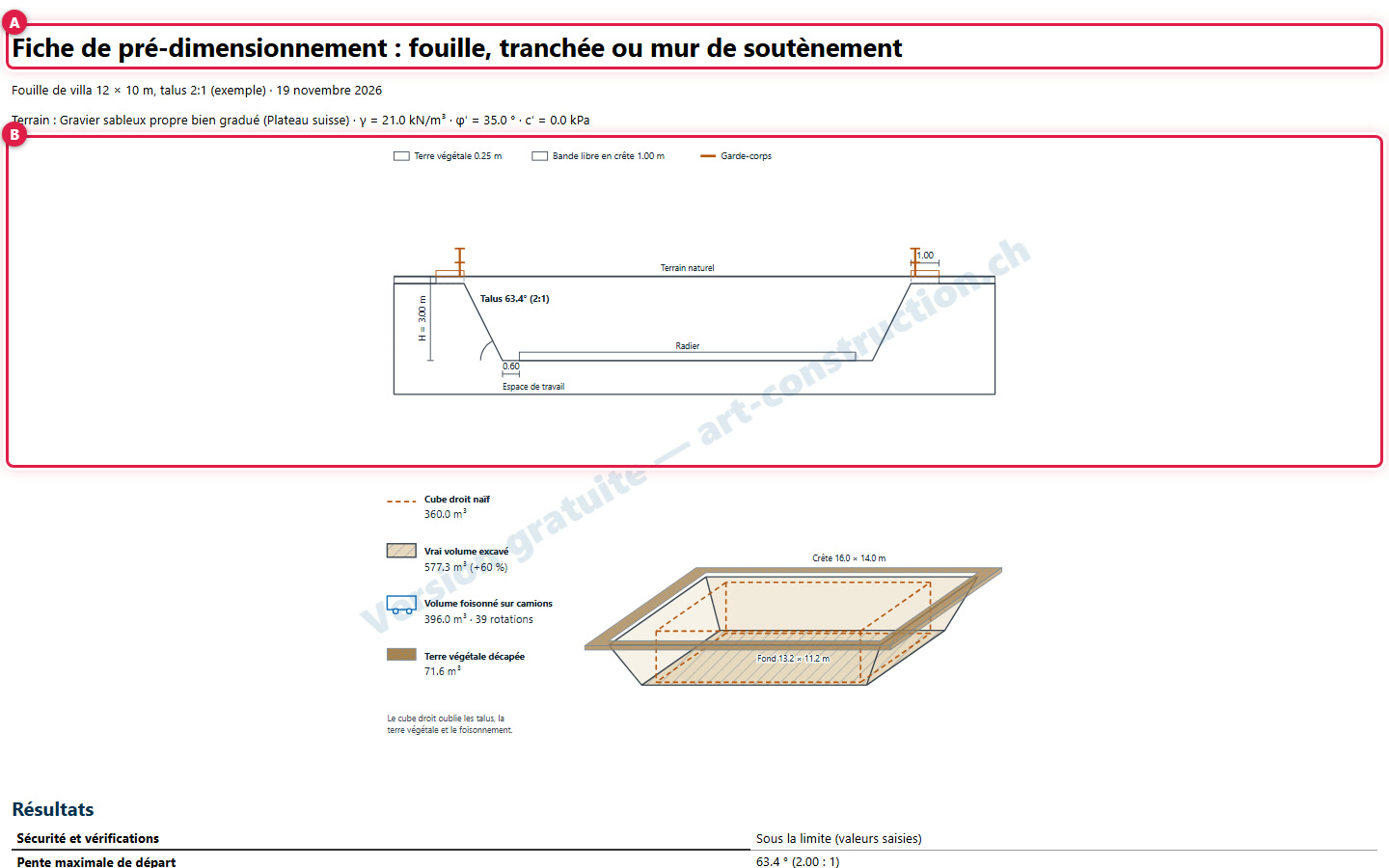
43Reading the printed sheet
The sheet (A) includes the example name, date and ground conditions, then (B) two diagrams of the structure, results, warnings, bill of quantities, assumptions and legal disclaimer. In the free version, it bears a watermark. This image is a screen preview of the sheet, not a photo of a printed page.
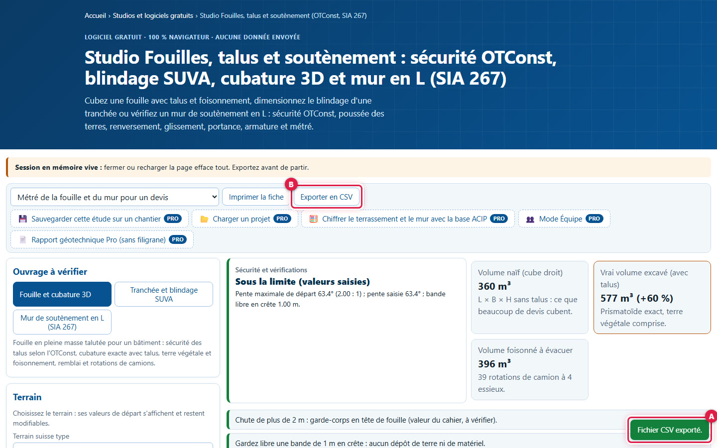
44Export to CSV
Click (B) Export to CSV: a message (A) confirms "CSV file exported.". The file contains the free version notice, the example, the date, the ground (γ, φ′, c′), the structure and its status, key figures, bill of quantities and the legal disclaimer. Its name ends with the example name.
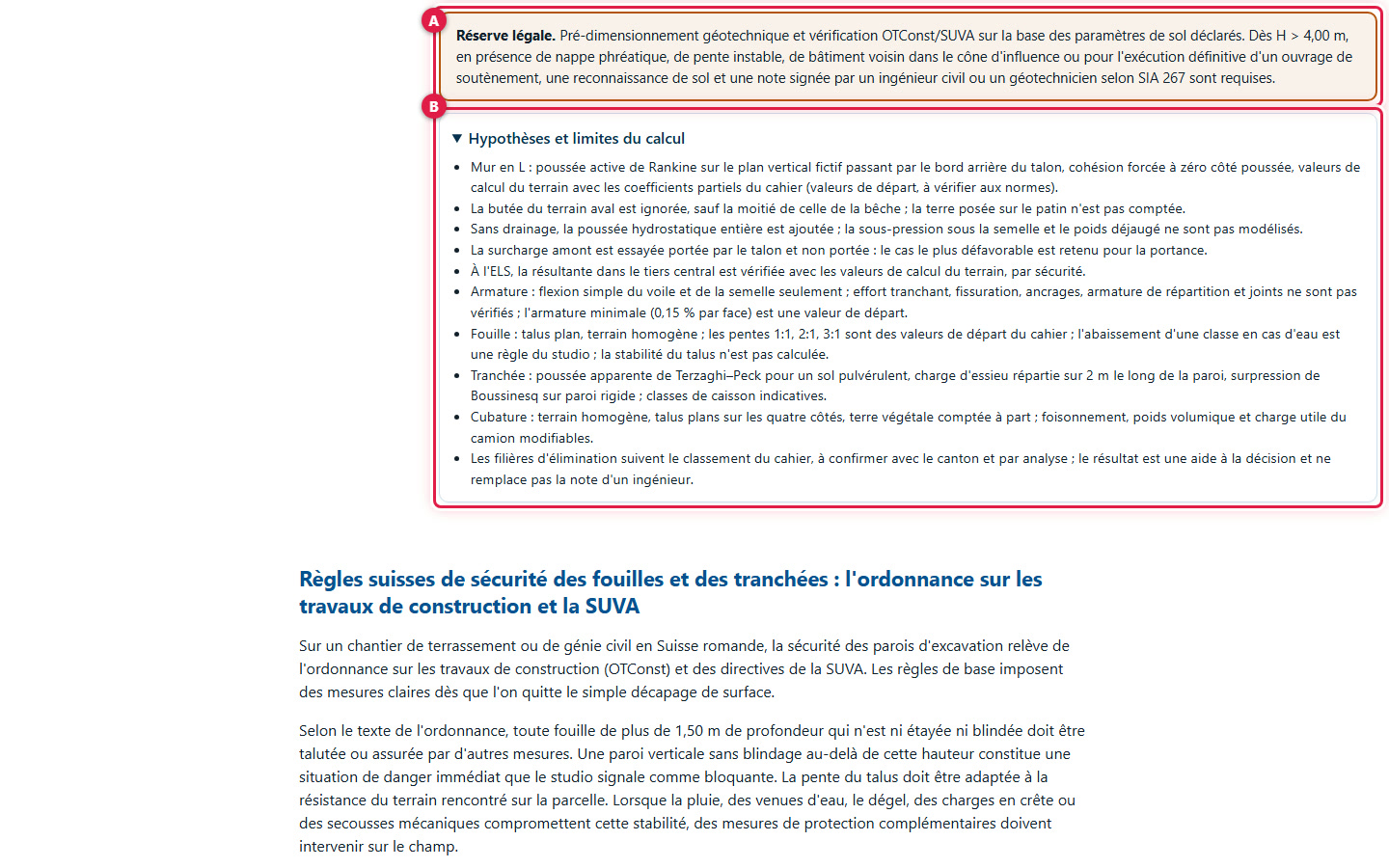
6. Legal disclaimer, assumptions and Pro buttons
45Read the legal disclaimer and assumptions
At the bottom of the page, (A) the legal disclaimer: preliminary sizing based on declared soil parameters; above 4.00 m, in the presence of groundwater, unstable slopes, neighbouring buildings or for the final execution of a retaining structure, a soil investigation and a signed note by a civil engineer or geotechnical engineer are required. (B) The assumptions and calculation limits, in ten points. Read them before relying on any figure.
46Locate the Pro buttons
The top bar has five buttons marked PRO (A): save the study to a construction site, load a project, price with the ACIP database, Team mode and watermark-free geotechnical report. They are part of the Pro offer (tenders, ERP, Portal). This guide does not describe them: this part has never been tested with a real server.
47Read the ACIP pricing window
The Unlock ACIP pricing button opens this window (A): the ACIP price database is never exposed in the free version, pricing is done on the server, in tenders. It offers links to tenders, the ERP and the construction site portal; the last button closes the window and takes you back to the studio. Nothing you have entered has been sent or saved by this window.

7. What this software does not do
- It does not replace the note of a civil engineer or geotechnical engineer, nor a site geotechnical report, nor the decision of the competent authority, and it does not give any legal advice.
- Excavation: the slope is plane and the ground homogeneous; slope stability is not calculated. The starting slopes 1:1, 2:1 and 3:1, the downgrading by one class in the presence of water and the guardrail from 2 m are studio notebook values or studio rules, not the ordinance text.
- The ground is chosen from 6 types. Their values (unit weight, friction, cohesion, bulking) are unofficial starting values, modifiable; neither layered ground nor groundwater is modelled.
- Trench: cohesionless soil, Terzaghi–Peck apparent pressure, axle load distributed over 2 m along the wall. The 3 trench box classes are indicative and without manufacturer names; soldier pile walls, sheet piles, and anchors are not covered.
- Wall: only the reinforced concrete L-shaped wall is covered. Rankine active pressure, cohesion forced to zero on the pressure side, downstream passive earth pressure ignored (except half of that of the shear key), uplift and buoyant weight not modeled. Neither gravity walls, nor gabions, nor anchored walls.
- Reinforcement: simple bending of the stem and base slab only; shear force, cracking, anchorages, distribution reinforcement, and joints are not checked.
- Soil disposal pathways are the studio workbook classification, to be confirmed with the canton and by analysis. No cantonal rules are applied: the studio has neither canton nor postal code to enter.
- The take-off gives quantities and their formulas, without prices and without ACIP codes.
- The free version saves no projects: everything is in RAM. The Pro buttons are not described in this guide: this part has never been tested with a real server.
- Tests were carried out on a computer, using Chrome. Firefox, Safari, touch screens, screen readers, and paper printing have not been tested.
Any questions? Send a request to support.