Studio Guide: Construction site layout plan, crane and scaffolding
This guide shows, step by step, how to set up a scaled construction site layout plan, check the crane, fire services access, logistics and facade scaffolding, and then export the result. The studio is free and runs in your browser.
1. Get started
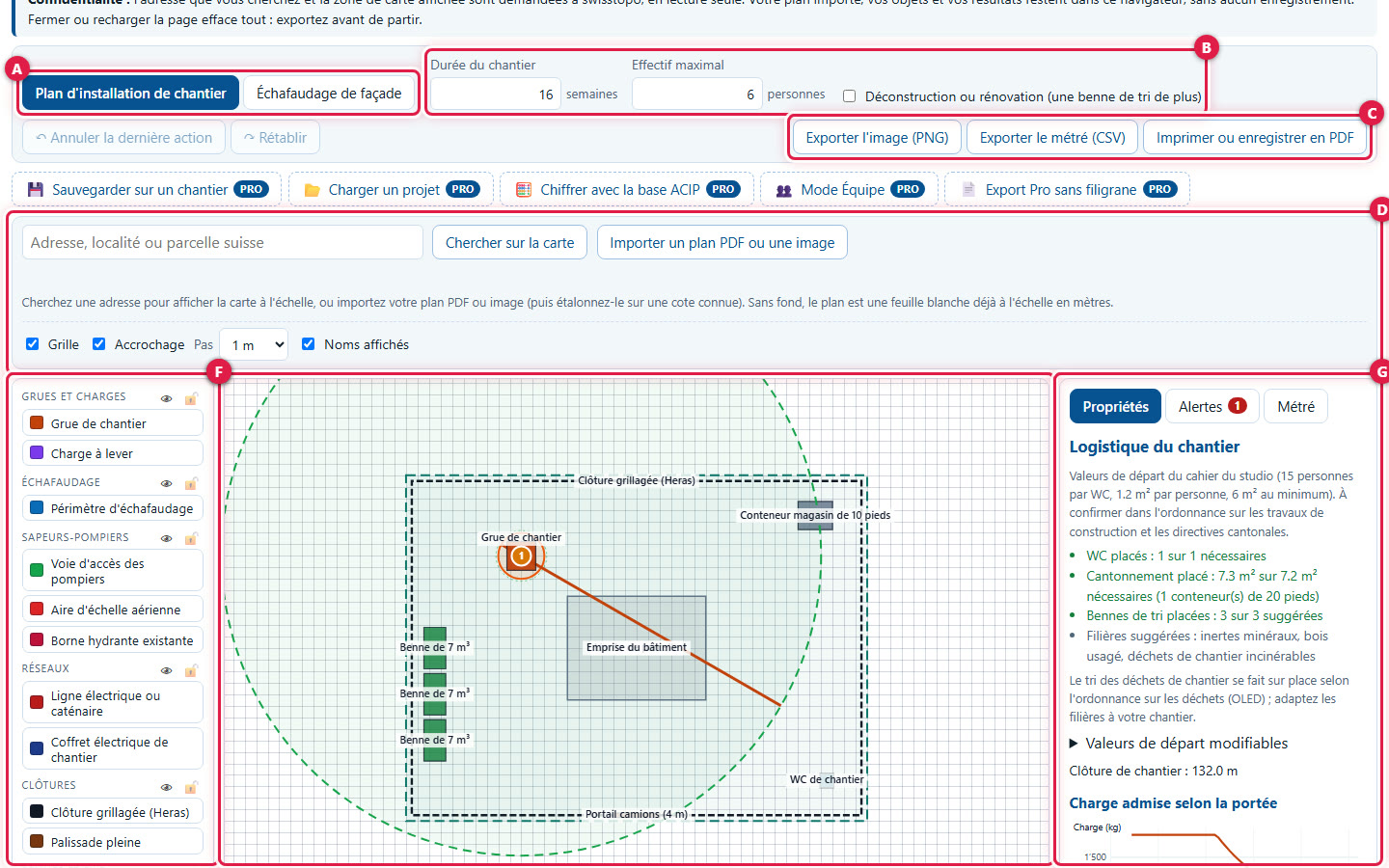
1Identify screen areas
Everything happens on a single page. At the top: (A) the two views, (B) the duration and workforce of the construction site, (C) the export buttons, (D) the background plan. Below: (E) the object palette, (F) the top-down plan, to scale, and (G) the Properties, Alerts and Quantities panels. Below the plan is the checklist.
The two views, Construction site layout plan and Facade scaffolding, work on the same project. Everything is calculated in your browser: nothing is saved, and closing or reloading the page erases the work. Export before leaving.
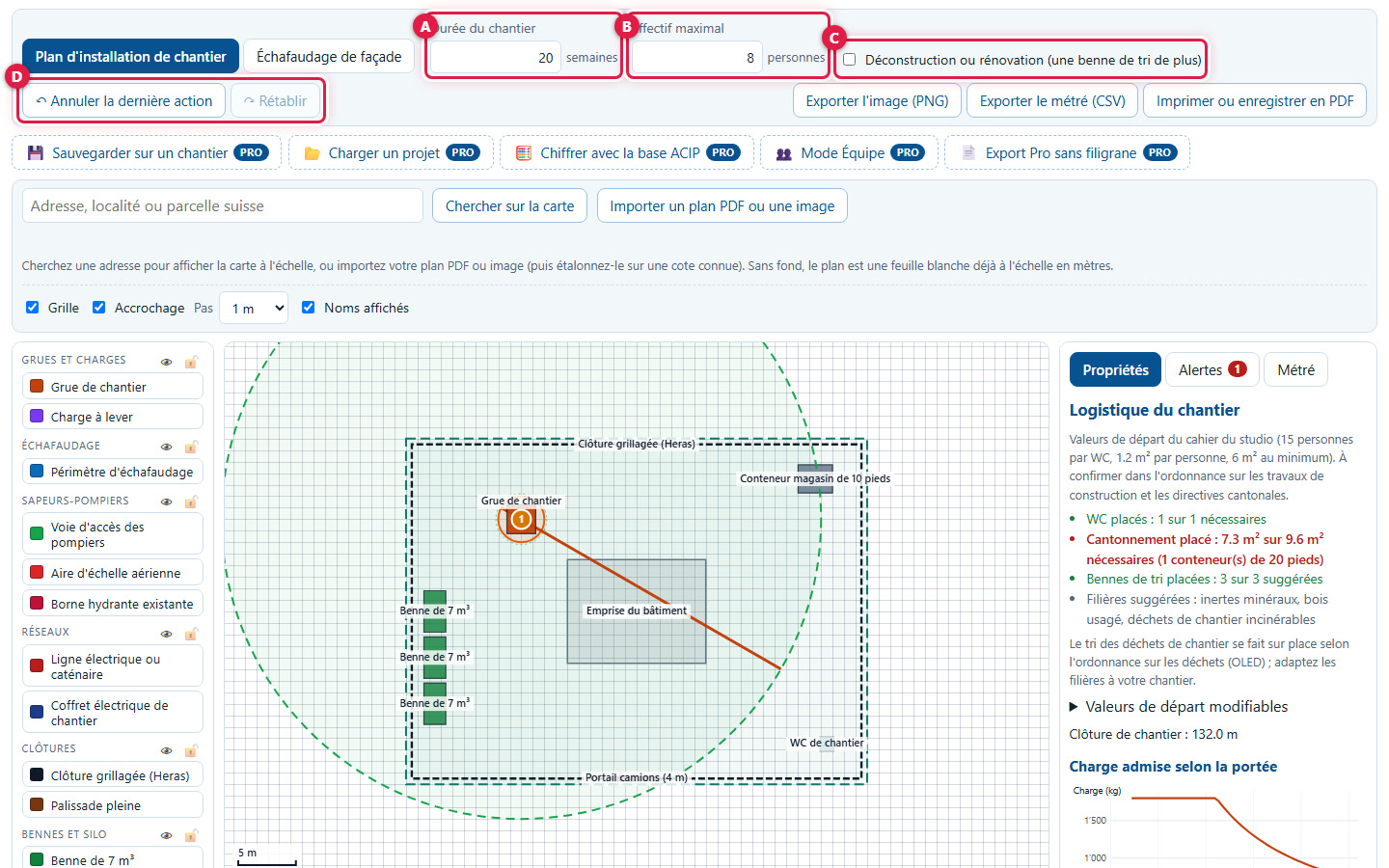
2Set duration and workforce
Enter (A) the construction site duration in weeks and (B) the maximum workforce in people. Check (C) the deconstruction or renovation box to plan for an additional sorting skip. These values are used to calculate the site toilets, site facilities and skips, and the rental in the quantities. Here: 20 weeks and 8 people.
(D) The Undo last action and Redo buttons undo and redo your actions: they activate as soon as the first change is made (200 levels).
2. The background plan
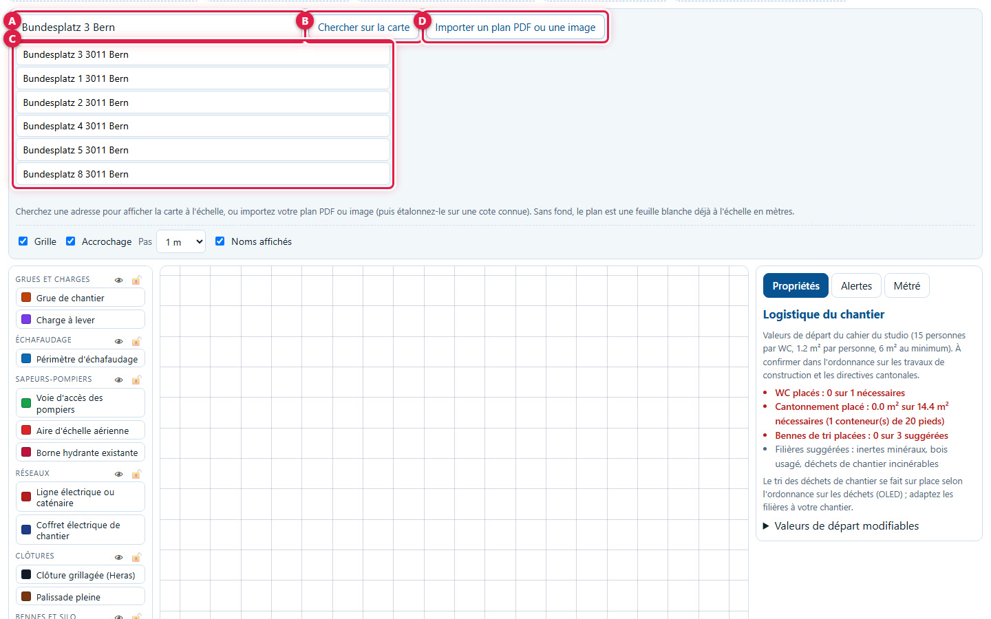
3Search for an address
Type an address, a locality or a Swiss plot (A), then click on Search on map (B) or press Enter. The list (C) suggests the found locations: click on the correct one. You can also import your own plan (D).
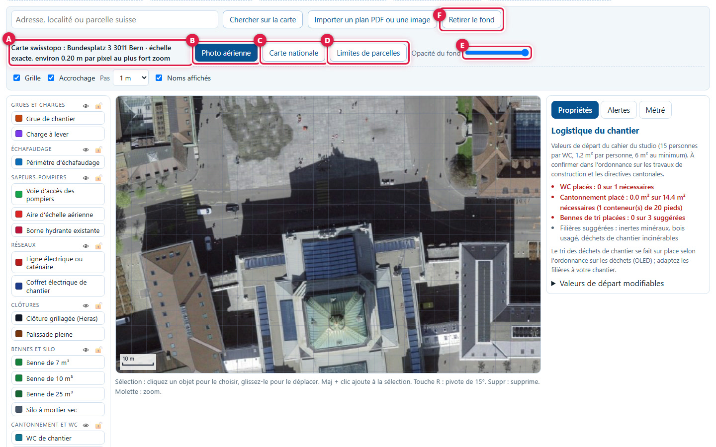
4Choose the map
The plan is placed on the swisstopo map, at exact scale (approximately 0.20 m per pixel at maximum zoom). (A) The title recalls the location and scale. Choose (B) the aerial photo, (C) the national map or (D) the plot boundaries in addition, then adjust (E) the background opacity. (F) The Remove background button returns to the blank sheet.
5Import your PDF or image plan
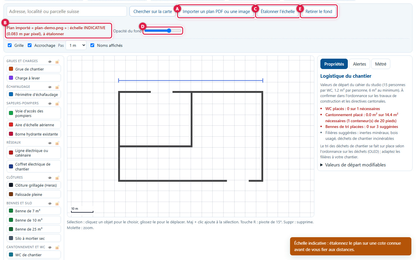
Click on Import a PDF plan or image (A) and choose a PDF, PNG, JPEG or WebP file. The file remains in your browser. (B) As long as the plan is not calibrated, its scale is only indicative (here 0.083 m per pixel). (C) The Calibrate scale button corrects the scale, (D) the opacity makes the plan more or less pale, (E) Remove background removes it.
A protected PDF requires its password, which remains in the browser. For a multi-page PDF, a field allows choosing the page.
6Calibrate scale on a known dimension
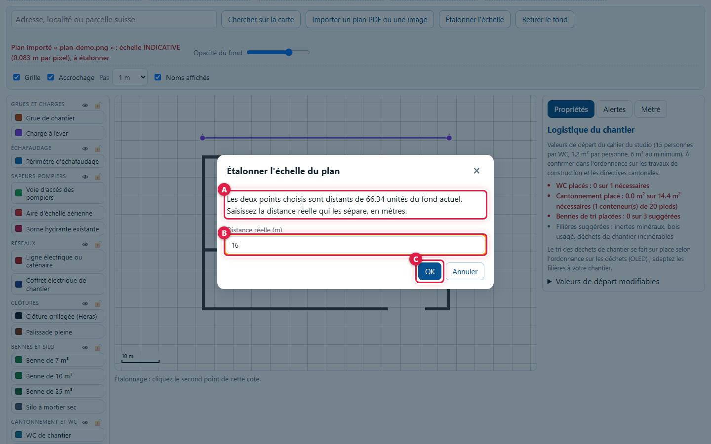
Click on Calibrate scale, then click the two ends of a known dimension on the plan: here the blue dimension of the example plan. In the window, (A) the studio gives the distance measured in the current background (66.34 units). Enter (B) the actual distance in meters (16 m here), then click on (C) OK.
7Check the calibrated scale
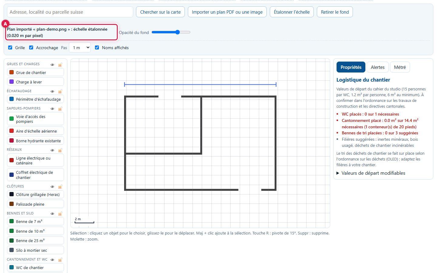
The background title (A) changes from "indicative scale" to "calibrated scale" (0.020 m per pixel). Distances, areas and plan checks can then be read at this scale. The view automatically reframes on the calibrated plan.
3. Placing and editing objects
8Choosing an object from the palette
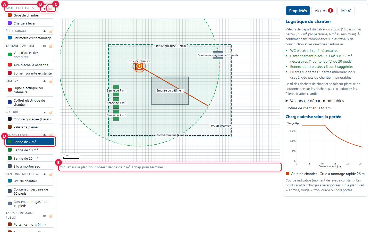
The palette groups objects by family. (A) Each family has a title, (B) an eye to hide or show its objects and (C) a padlock to lock them. (D) Click on an object (here a 7 m³ skip): it is armed. (E) The help line tells you what to do: click on the plan to place it, Esc to finish.
There are twenty-six to-scale objects: crane and load to lift, scaffolding perimeter, fire appliance access route and aerial ladder platform area, fire hydrant, power line and electrical cabinet, fences, gates, pedestrian tunnel, concrete mixer truck, skips, silo, site toilet, containers and zones. Hover the mouse over an object to read its description.
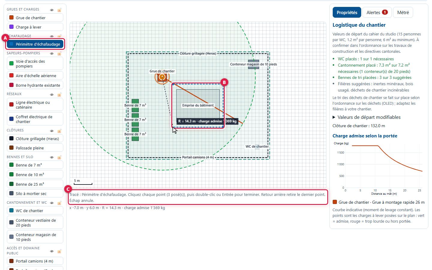
9Drawing a fence, a route or a zone
Fences, the fire appliance access route, the power line, the scaffolding perimeter and zones are drawn. Choose the object (A), click each point (B), then double-click or press Enter to finish. (C) The help line counts the placed points: Backspace removes the last one, Esc cancels.
10Select, move and rotate
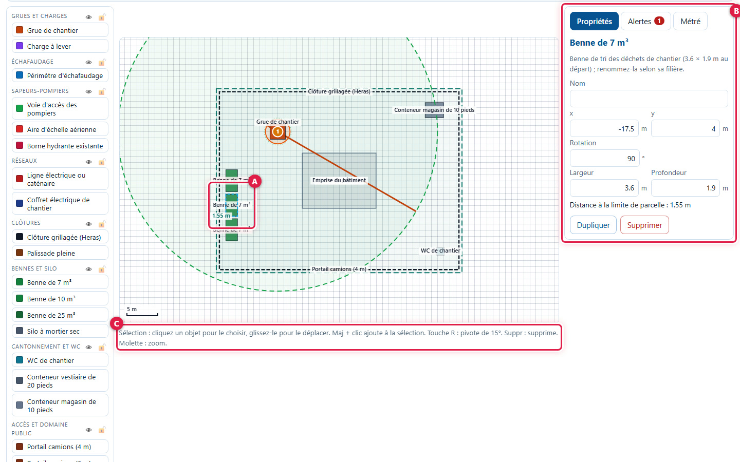
Click an object to select it (A): its properties open on the right (B). Drag it to move it: it snaps to nearby vertices and to the grid. Shift + click adds an object to the selection. The R key rotates by 15° (Shift + R in the other direction), Ctrl + D copies, Delete deletes, Ctrl + Z undoes and Ctrl + Y redoes. The mouse wheel zooms the plan. (C) The helper line reminds you of these actions.
11Modify an object's properties
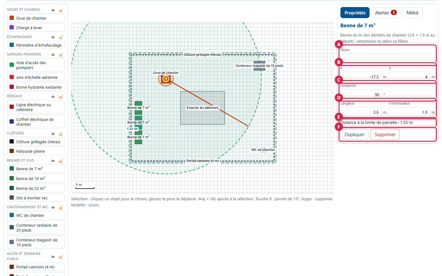
The Properties panel provides (A) the name, (B) the x and y position in metres, (C) the rotation in degrees and (D) the dimensions. (E) If a plot boundary is drawn, the distance to this boundary is displayed (here 1.55 m); it turns red when the object leaves the plot. (F) Duplicate and Delete act on the selected object.
A value is applied when you leave the field (Enter or Tab key). Illegible text is flagged and ignored.
12Hide or lock a family
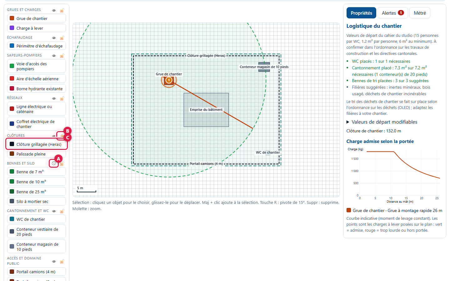
(A) The eye hides all objects in a family: here the skips have disappeared from the plan. (B) The padlock locks a family: its objects can no longer be selected or moved, here the fences (C). Click again to revert.
13Adjust grid and names
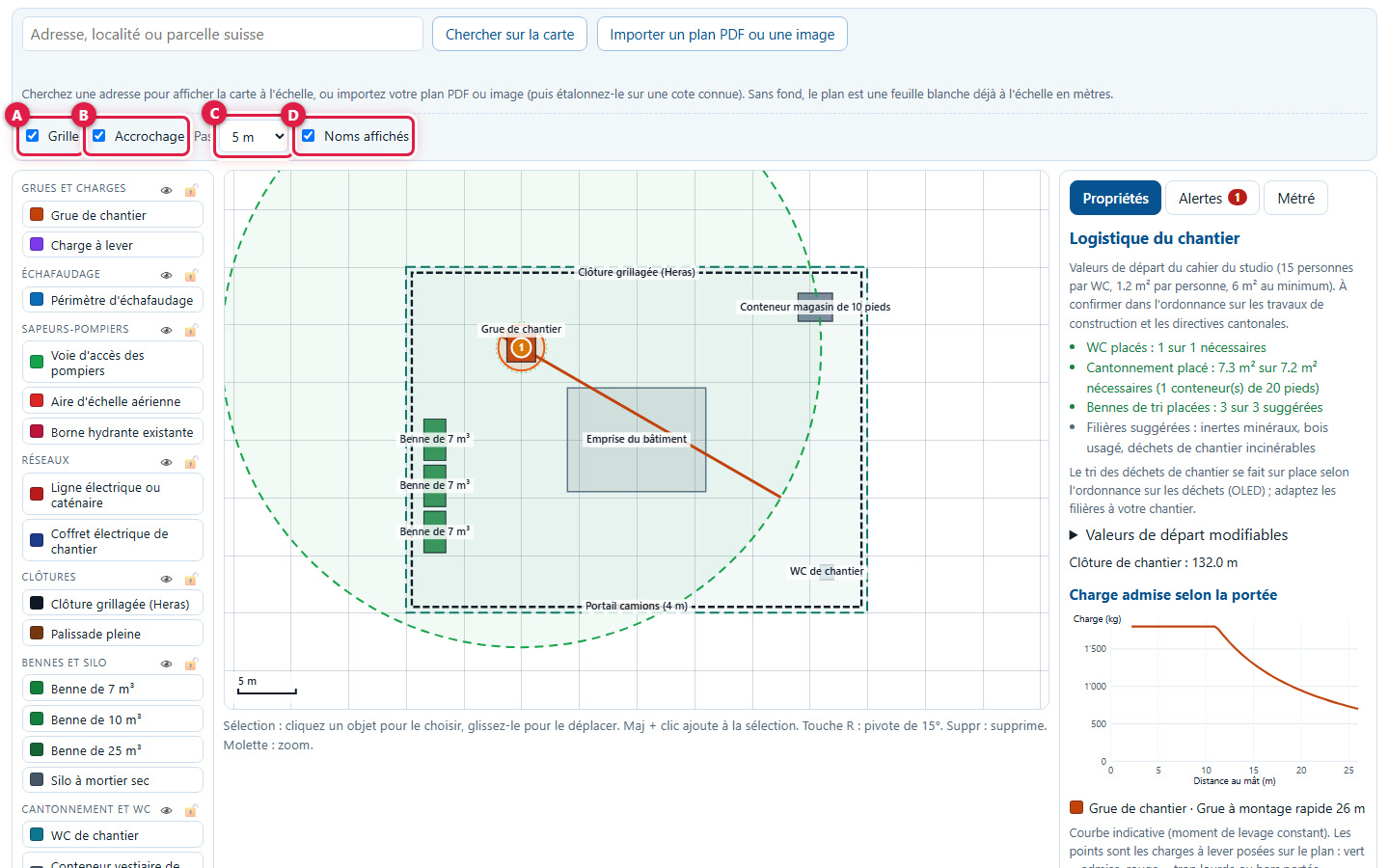
Below the background plan: (A) the grid is shown or hidden, (B) snapping aligns points to nearby vertices or to the grid, (C) the grid step can be chosen between 0.5, 1, 2, 5 and 10 m (here 5 m), (D) object names are displayed or not.
4. The crane
14Choose model and jib direction
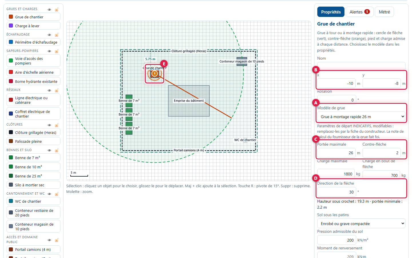
Place a crane, then click it: (A) the list offers eight generic models, from spider mini-crane to 60 m tower crane, without any brand. (B) Maximum radius and counter-jib, (C) maximum load and jib-end load, (D) jib direction in degrees. (E) On the plan, the green circle is the radius, the orange circle the counter-jib and the line the jib.
15Read the permissible load at the cursor
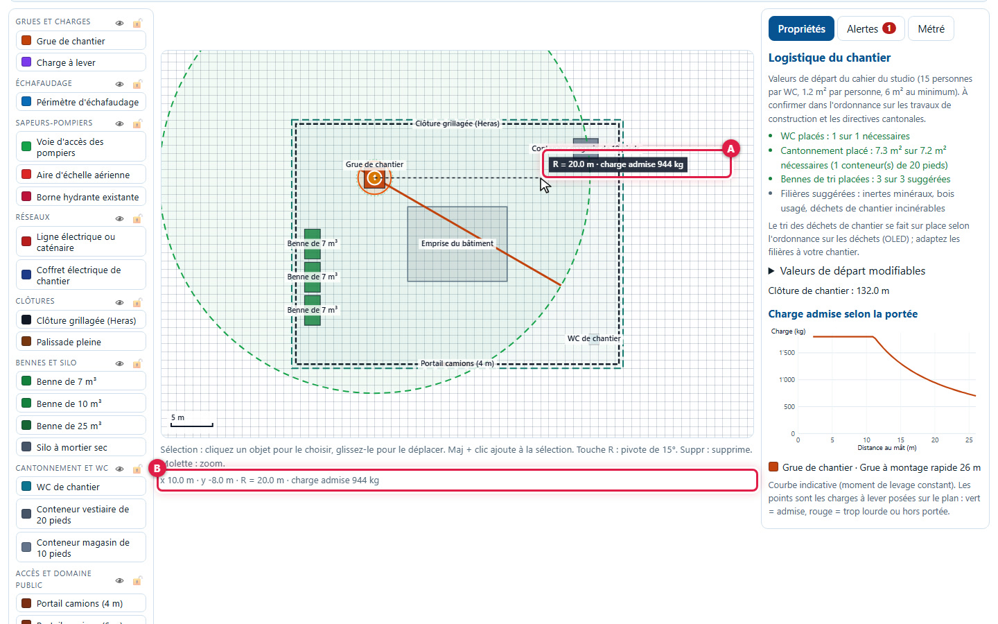
Hover over the plan: (A) a tooltip and (B) the status bar below the plan give the distance to the mast and the permissible load at this location. Here, at 20.0 m from the mast: 944 kg. The further away, the less the crane lifts. Beyond the maximum radius, or too close to the mast, the studio writes "out of crane range".
16Read supports and load chart
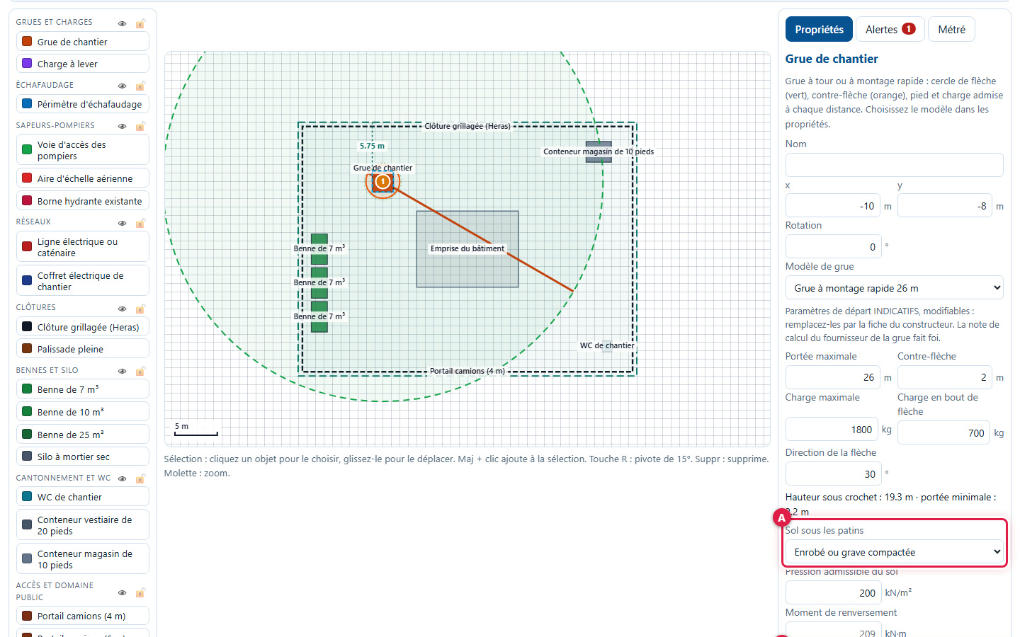
Further down in the crane properties: (A) the ground under the outriggers (asphalt, soil or entered value) and its permissible pressure, (B) the maximum reaction of an outrigger (103 kN here) and the minimum load-spreading plate (0.75 × 0.75 m), (C) the curve of the permissible load according to the distance to the mast. The points on the curve are the loads to lift placed on the plan: green if they pass, red otherwise.
17Place a load to lift
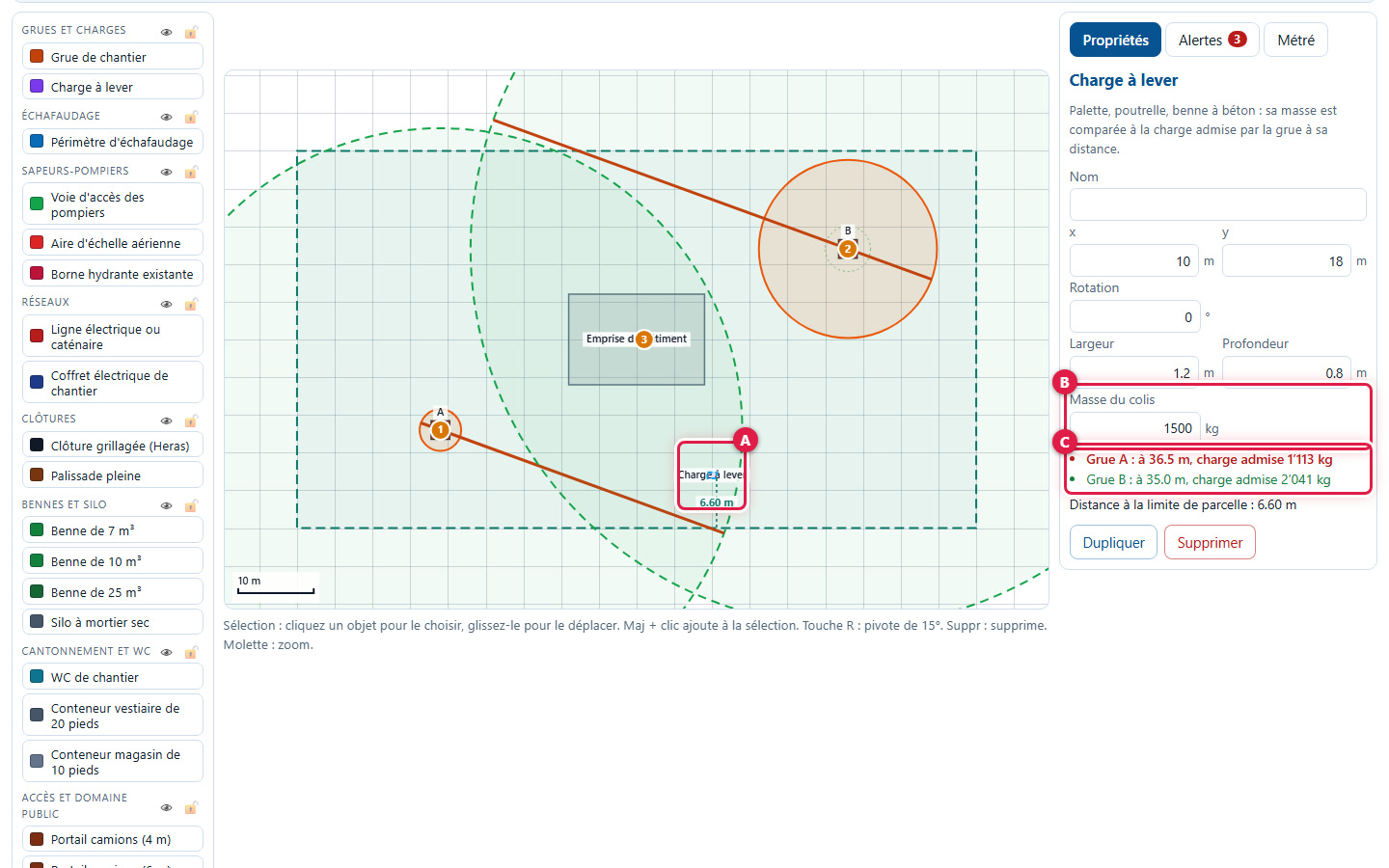
Choose Load to lift from the palette and click on the plan (A). Enter its mass (B) (here 1500 kg). (C) For each crane, the studio gives the distance to the mast and the permissible load at this distance: crane A allows 1’113 kg at 36.5 m (too little), crane B allows 2’041 kg at 35.0 m (enough). The check is passed if at least one crane can lift the load.
18Read crane alerts
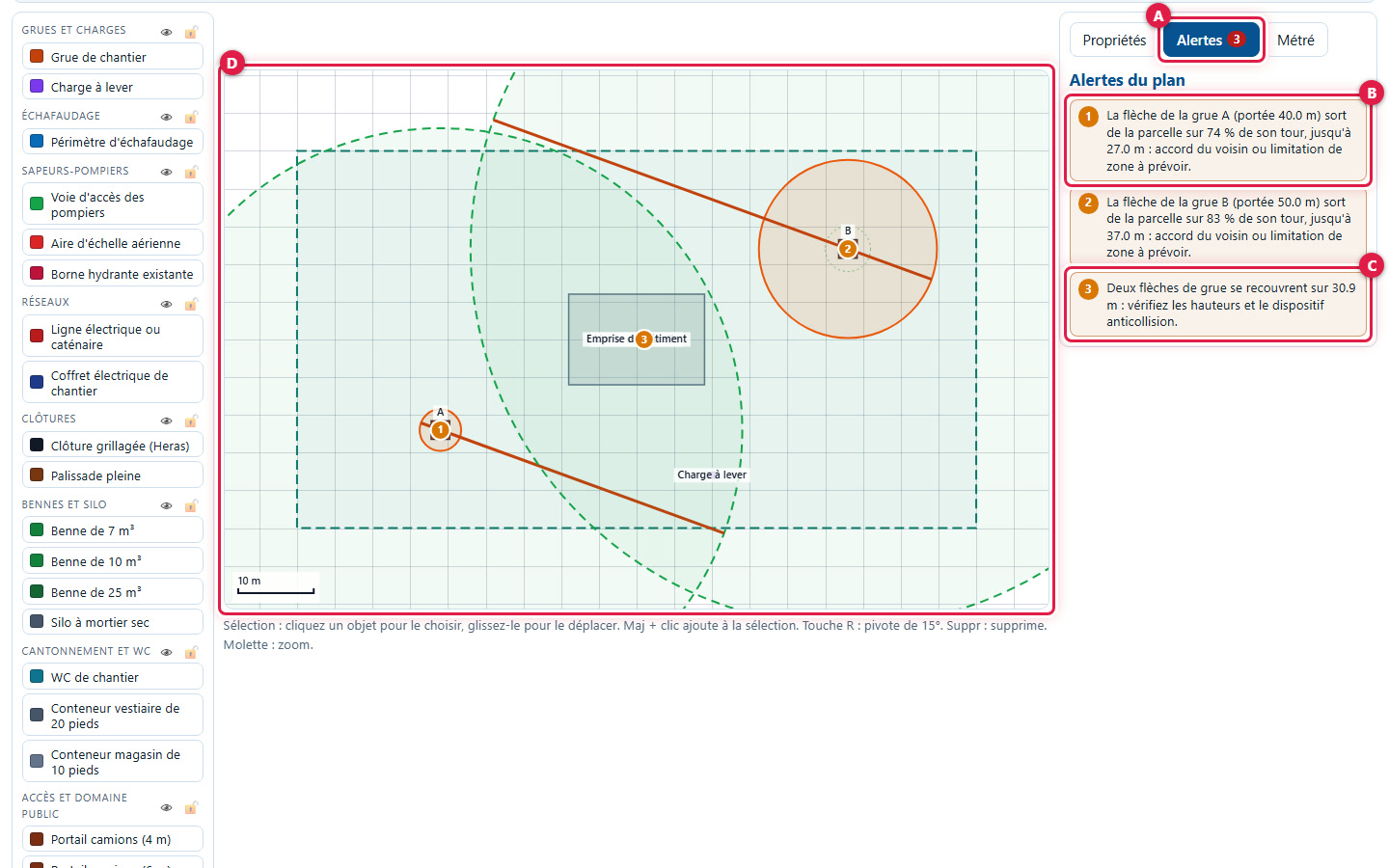
The Alerts tab (A) lists the alerts, numbered and coloured according to their severity; a badge indicates their number. (B) Crane A's jib extends outside the plot for 74 % of its rotation, up to 27.0 m: neighbour agreement or zone limitation must be arranged. (C) Two crane jibs overlap over 30.9 m: check the heights and the anti-collision device. (D) The circles are read on the plan.
19Jump from alert to object
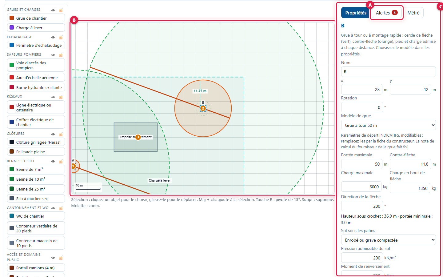
Click an alert: the relevant object is selected and the plan centres on it (B), and its properties open (C). Return to the list using the Alerts tab (A).
20Keep distance from a power line
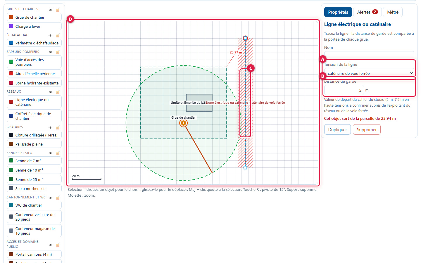
Draw the power line or catenary, then choose (A) its voltage (low or medium, railway catenary, high voltage) and (B) the safety clearance. Default values are 5 m, and 7.5 m for high voltage: to be confirmed with the grid or railway operator. (C) The hatched area marks the clearance zone around the line.
In the example, the jib passes 3.00 m from the line while the entered clearance is 5.00 m: the Power lines and railway line (crane safety clearance) line turns red.
5. Fire services access
21Draw the access route
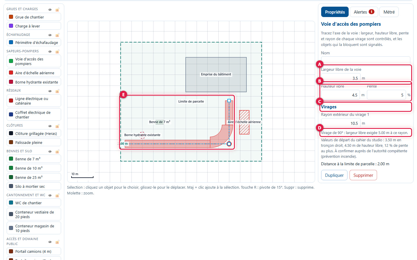
Draw the axis of the route (E). The panel gives (A) the clear lane width, (B) the clearance height and gradient, and (C) the bend section, with the outer radius of each. (D) Under each radius, the studio indicates the required width at that radius: here 5.00 m. Default values are 3.50 m on straight sections, 4.50 m clearance height and a maximum of 12 % gradient.
22Place the ladder platform area and fire hydrant
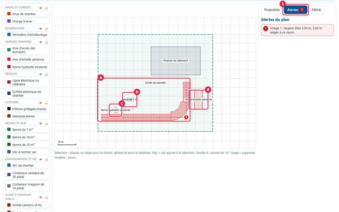
(A) The route. (B) The aerial ladder platform area (11 × 4.5 m initially) must remain clear. (C) A 3 m diameter zone around the fire hydrant must remain clear. (D) An obstructing object (skip, fence, crane base within the route envelope) is flagged. (E) In the Alerts tab, the alert states that bend 1 has 3.50 m of clear width for 5.00 m required.
6. Logistics and public land
23Count toilets, site accommodation and skips
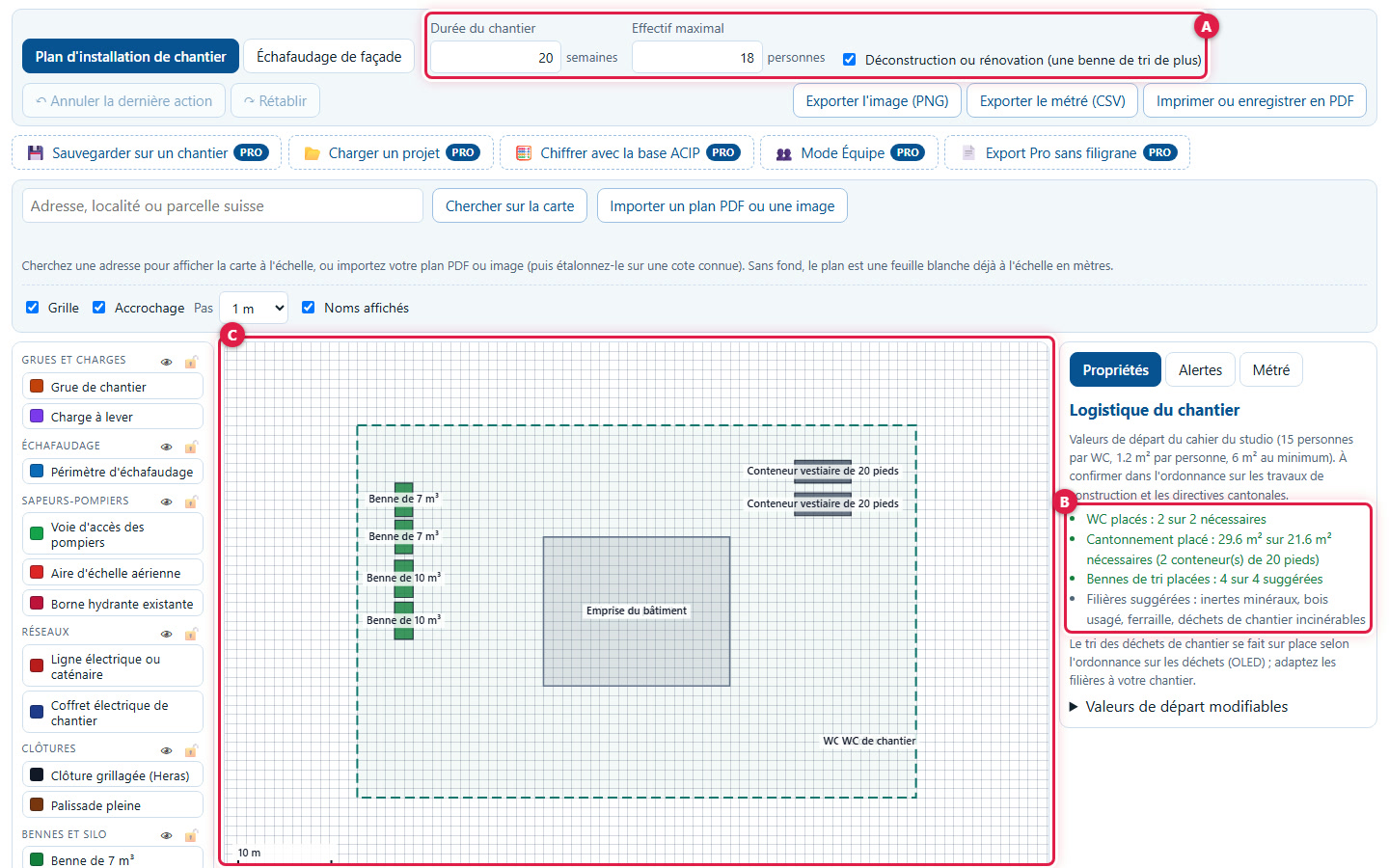
When no object is selected, the Properties panel shows logistics. (A) Duration, workforce and renovation: here 18 people for 20 weeks. (B) The studio compares what you have placed with what is required: toilets 2 out of 2, site accommodation 29.6 m² out of 21.6 m² (2 20-foot containers), sorting skips 4 out of 4, with suggested streams. (C) The objects are visible on the plan.
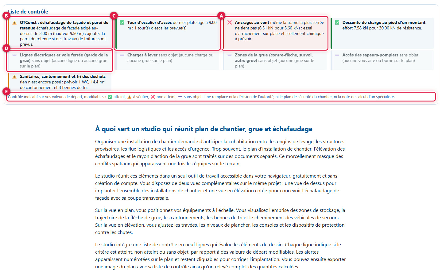
The Sanitary facilities, site accommodation and waste sorting line in the checklist is green when everything is placed, orange when something is missing: it is never red.
24Modify default values
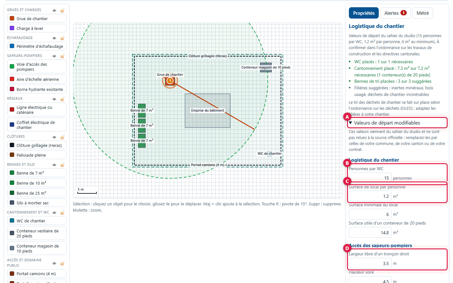
Open (A) Editable default values at the bottom of the panel. (B) People per toilet (15), (C) room area per person (1.2 m²), minimum area (6 m²), usable area of a 20-foot container; then, for the fire services, (D) clear width of a straight section, clearance height, gradient, turning radii, ladder platform area and hydrant zone. The checks use your values immediately.
25Count public land
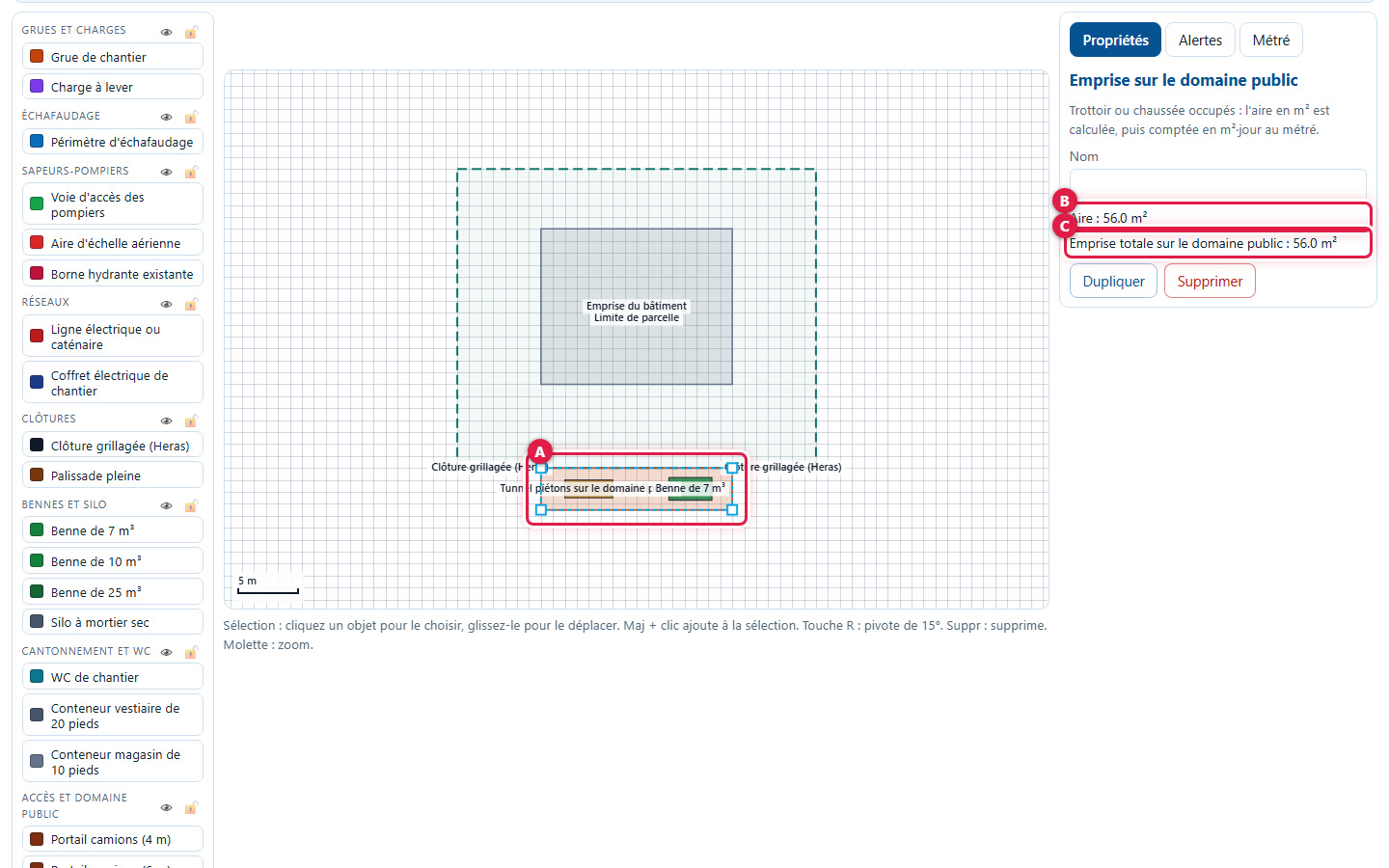
Draw Public land footprint (A) (occupied pavement or roadway). (B) The studio calculates its area (56.0 m²) and (C) the total public land footprint. The quantities list counts it in m²·day: area × 7 days × construction site duration, here 56.0 m² × 7 × 12 weeks = 4’704 m²·day.
7. Facade scaffolding
26Trace scaffolding perimeter
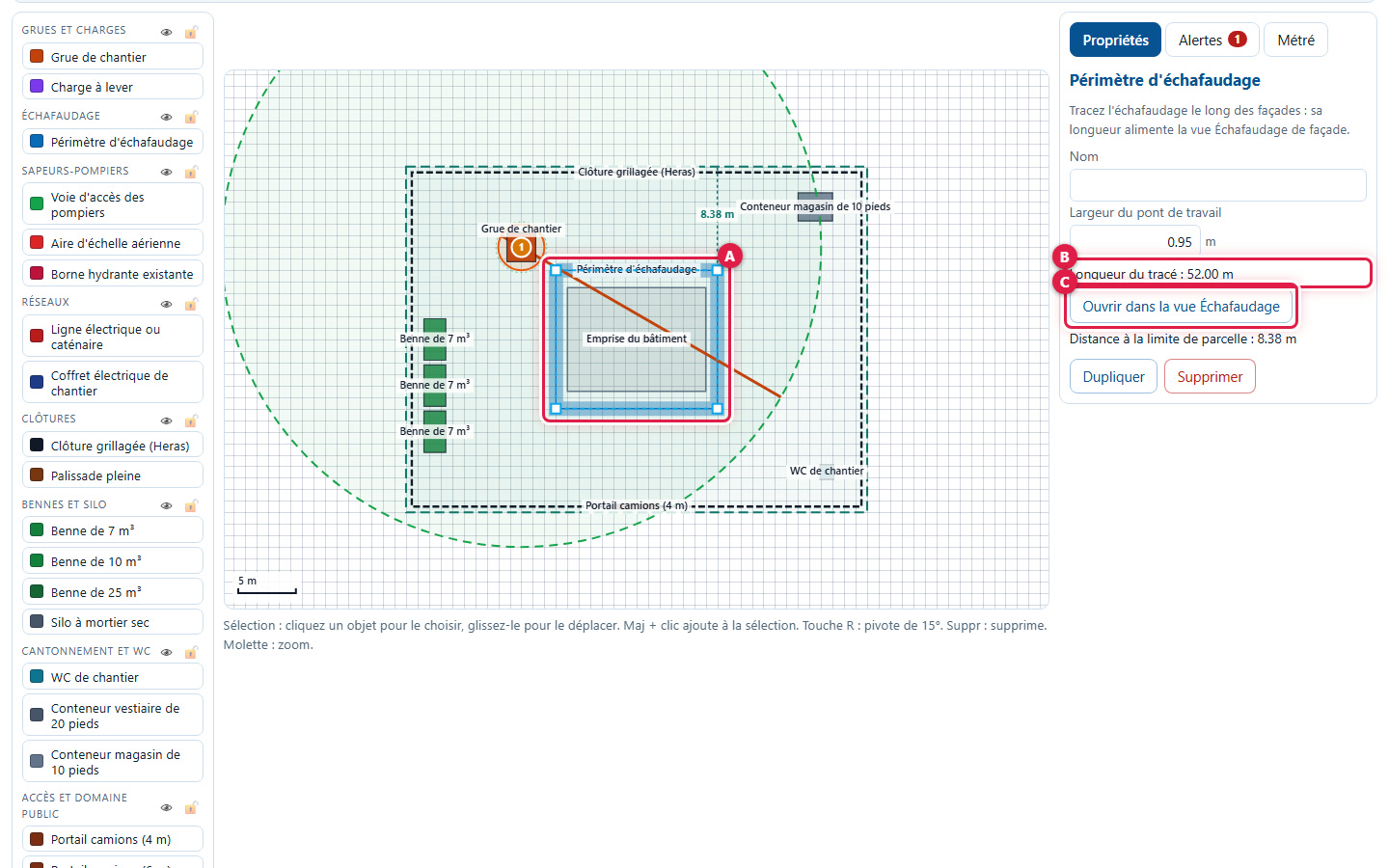
Select Scaffolding perimeter and trace it along the facades, like a fence. (A) The trace is displayed in blue. (B) The panel gives its length (52.00 m here) and the width of the working platform. (C) The Open in Scaffolding view button opens the Facade scaffolding view: the facade length is then read from the plan.
27Adjust scaffolding
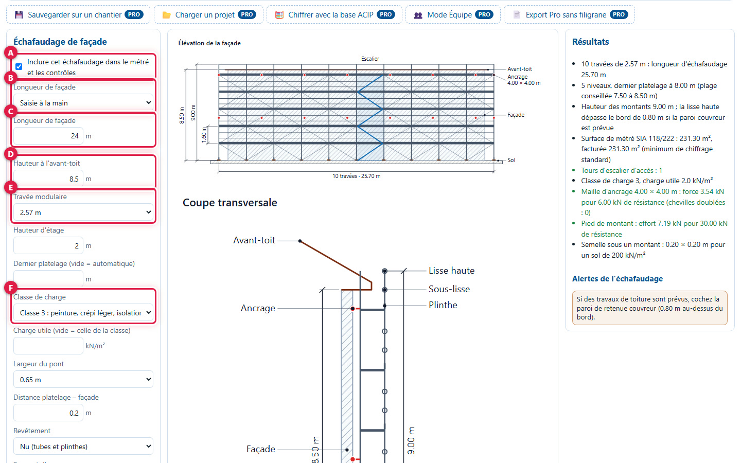
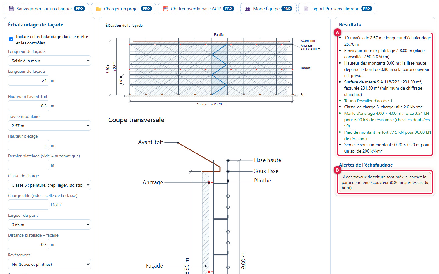
In the Facade scaffolding view, the left column adjusts the scaffolding. (A) Include scaffolding in quantities and checks. (B) Length source: manual entry or sum of plan traces. (C) Facade length (24 m here), (D) height to eaves (8.5 m), (E) modular bay and (F) load class.
Lower down: storey height, top platform (empty = automatic), payload, platform width, platform-facade distance, cladding, anchor base material, anchor resistance, wind pressure, facade shielding, ground and fall height threshold. Reset to default values resets default values.
28Read elevation and cross-section
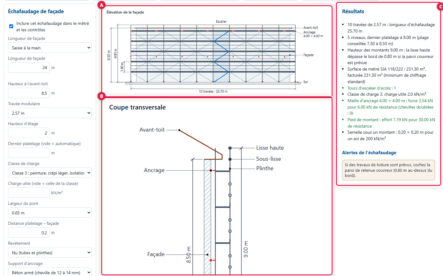
(A) The dimensioned elevation shows the facade with its bays, levels, staircase and anchorages (red points. (B) The cross-section labels top guardrail, midrail, toe board, anchorage, platform, base plate and distance to the facade. (C) Results are on the right.
29Read results
(A) The list gives 10 bays of 2.57 m (length 25.70 m), 5 levels with top platform at 8.00 m (recommended range from 7.50 to 8.50 m), upright height (9.00 m), quantities surface (231.30 m²), access stair towers (1), load class 3, anchor grid (4.00 × 4.00 m: 3.54 kN for 6.00 kN resistance), upright base (7.19 kN for 30.00 kN) and base plate (0.20 × 0.20 m for ground of 200 kN/m²). (B) Scaffolding alerts are displayed below.
30Configure wind anchorages
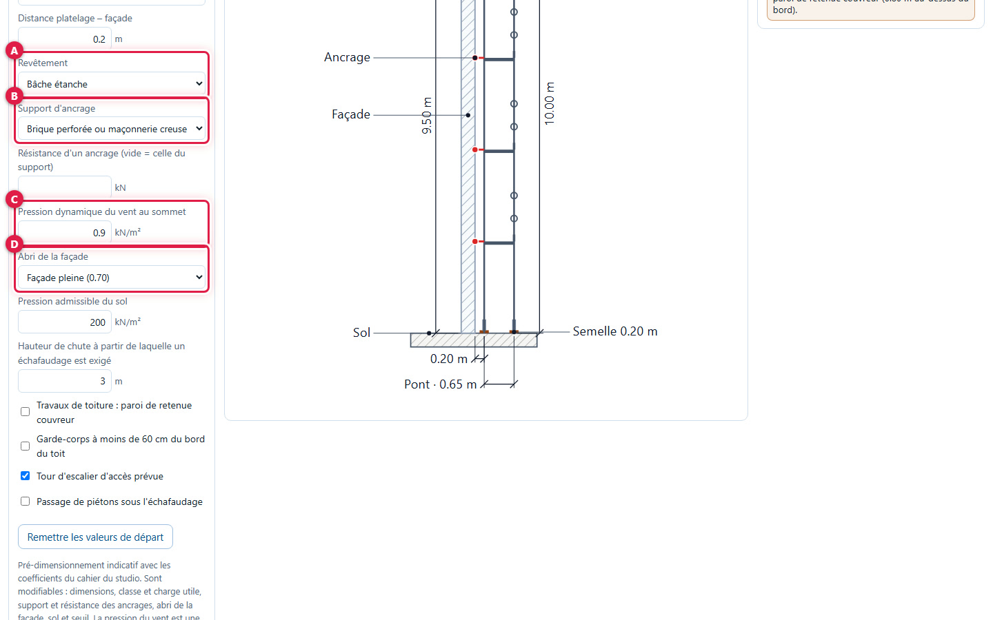
Choose (A) the cladding (bare, dust protection net, weatherproof tarpaulin), (B) the anchor base material (reinforced concrete, perforated brick, timber), (C) the peak dynamic wind pressure at roof level and (D) the facade shielding (solid or open facade). The wind pressure is ENTERED: the starting value (0.9 kN/m²) is only an illustration to be replaced by the one from standard SIA 261 for your location.
31Read the anchorage grid
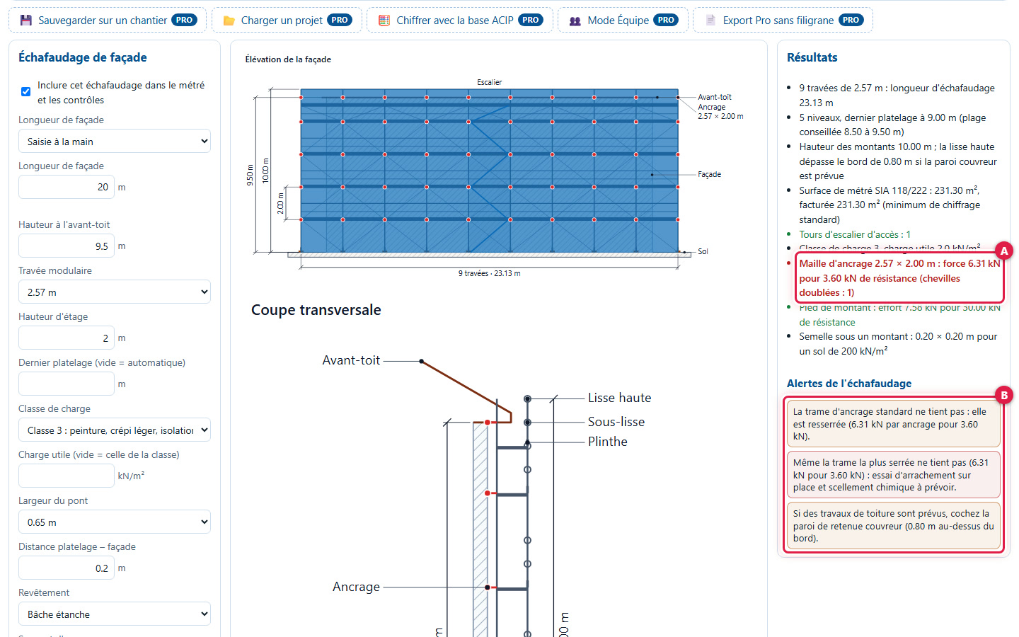
If the standard anchorage pattern does not hold, the studio tightens it automatically: here the grid becomes 2.57 × 2.00 m (A), with 6.31 kN per anchor for 3.60 kN of resistance. (B) The alerts indicate that the pattern is tightened and, if even the tightest pattern does not hold, that an on-site pull-out test and chemical anchoring must be planned.
32Plan the roofer's screen
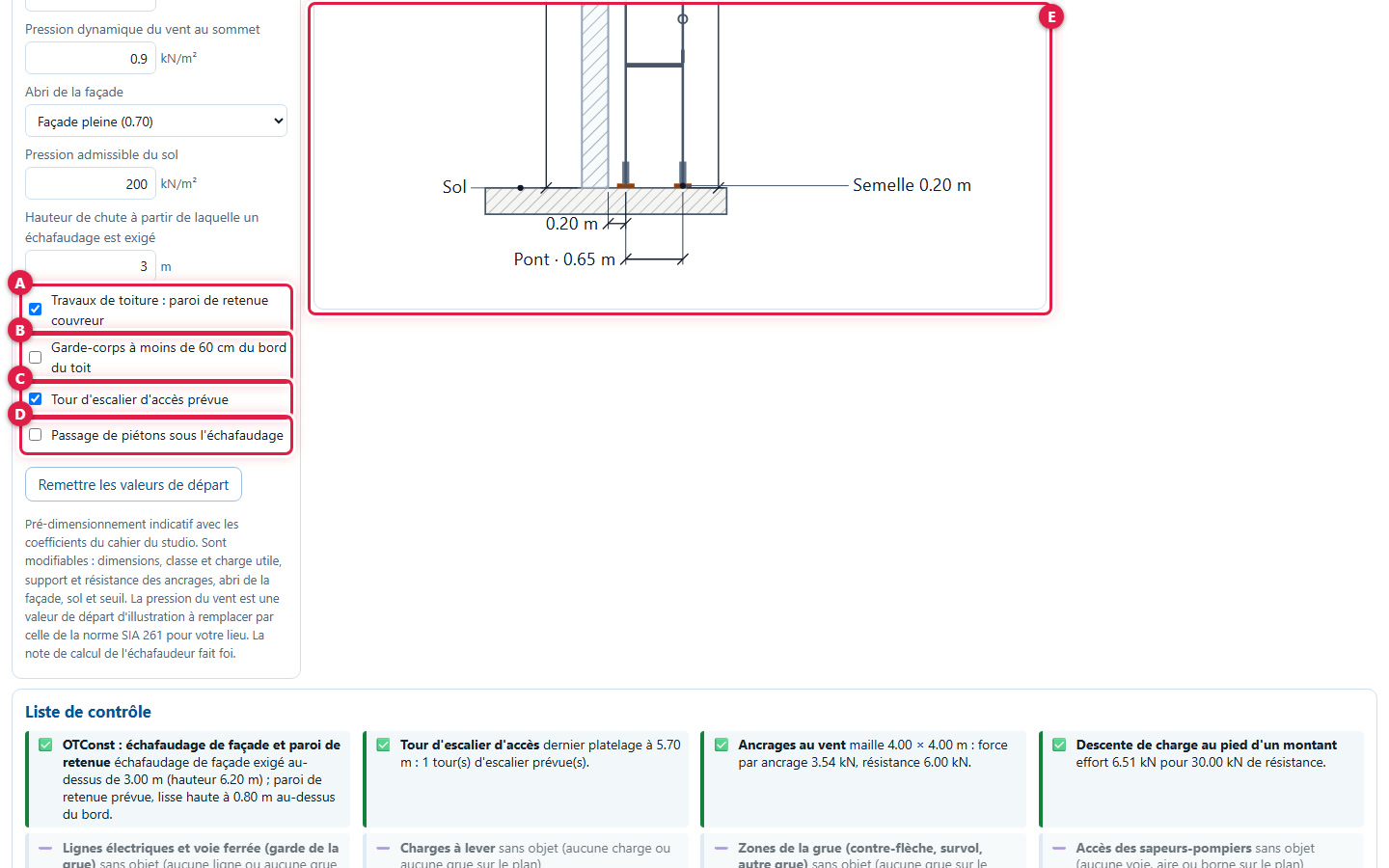
Check (A) the roofer's screen for roofing work: the top guardrail then extends 0.80 m beyond the edge, or 1.00 m if (B) the guardrail is less than 60 cm from the edge. (C) Check the planned access stair tower and (D) the pedestrian walkway under the scaffolding (the studio reminds to protect the walkway). (E) The section shows the screen.
8. Checks, quantities and exports
33Read the checklist
Nine lines below the plan update with every action: achieved (green), to check (orange), not achieved (red) or not applicable (grey). Here, (A) Wind anchors is red, (B) OTConst: facade scaffolding and containment wall is orange, (C) Access stair tower is green and (D) Power lines and railway line (crane safety clearance) is not applicable. (E) A reminder states that this check is indicative.
34Read the quantities
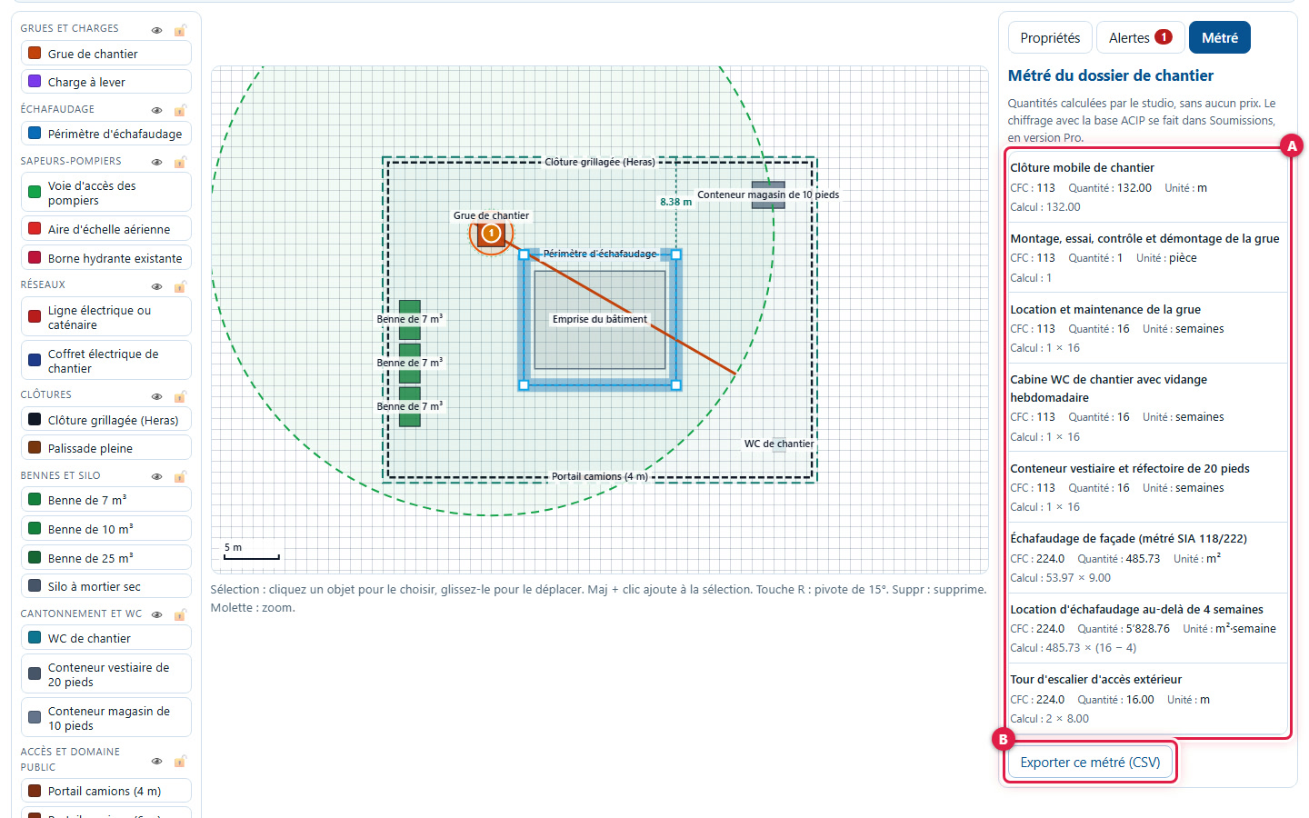
Open the Quantities tab. (A) Each item is a record with its name, its CFC, its quantity, its unit and its calculation: mobile fence, crane (assembly and rental), site toilet, container, facade scaffolding and its rental, stair tower, public land. Here, 8 items and 485.73 m² of facade scaffolding. The quantities have no prices. (B) Export this bill of quantities (CSV) downloads the quantities.
35Export image, quantities or PDF
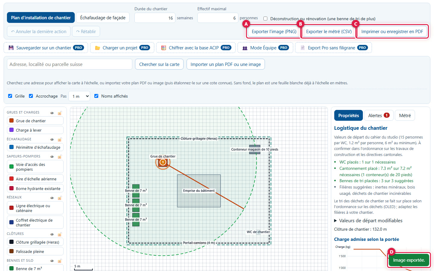
(A) Export image (PNG) downloads a single image: header, plan, checklist, quantities and notices, with the free version watermark. In view Facade scaffolding, it contains the elevation, section and results. (B) Export quantities (CSV) downloads the quantities. (C) Print or save as PDF opens the browser print. (D) A message confirms the export.
36Understand PRO buttons
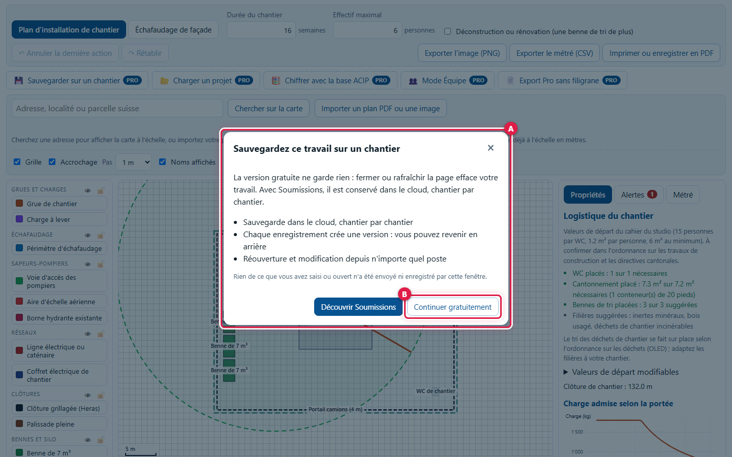
The five buttons marked PRO (Save to a construction site, Load a project, Cost estimation with the ACIP database, Team Mode and Pro export without watermark) are not active in the free version. Each opens an information window (A): for example, the free version keeps nothing, closing or refreshing the page erases your work. (B) Continue for free closes the window: nothing you have entered is sent or saved.
9. What this software does not do
- It replaces neither the calculation note from the crane supplier or scaffolder, nor the site safety plan, nor the decision of the competent authority, and it provides no legal advice. The plan is not an engineer's plan and is not reviewed by the authority.
- It works in top view only: jib heights do not clear any alerts. The load chart follows a constant lifting moment: it is not a manufacturer's load diagram, and the eight crane models are generic, unbranded, with indicative starting values.
- Wind pressure is entered by you: the studio does not calculate it according to the location. Anchorages and standard bases are to be read using the coefficients in the studio's workbook.
- Default values (lane width, clearance height, gradient, radii, ladder area, people per toilet, power line safety clearances, etc.) are not checked against the AEAI directive, the network operator or the ordinance: confirm them before relying on them.
- The background map comes from swisstopo and requires an internet connection. A PDF or image plan must be calibrated against a known dimension: the studio does not read the scale of a PDF, and a heavily zoomed PDF becomes blurry.
- The studio gives no prices and prices nothing. PRO buttons are not available in this version: there is no saving, no reopening of a project, and no sending to the quote.
- Tests were carried out on a computer using Chrome. Firefox, Safari, touchscreens and paper printing were not tested.
A question? Send a request to support.